
Adaptive impedance matching apparatus and method for wireless power transfer

Active Publication Date: 2022-06-16
HYUNDAI MOBIS CO LTD
View PDF13 Cites 0 Cited by
  • Summary
  • Abstract
  • Description
  • Claims
  • Application Information

AI Technical Summary

Benefits of technology

The present invention provides a method for matching impedance efficiently based on changes in distance and positions using a feedback loop. This method ensures maximum transmission efficiency. An apparatus and method for immediate impedance matching according to changes in distance and positions is also provided.

Problems solved by technology

However, in the case of a conventional impedance matching method, there is a limit in responding to a change in the distance or positions between TX / RX coils.
Specifically, in the case of wireless charging of an electric vehicle, which is one of the magnetic resonance application fields, since a position of a vehicle, which is a receiving terminal, may not be specified, and charging should be performed as soon as possible, a problem in that impedance matching which achieves immediate and maximum transmission efficiency is required should be solved.

Method used


Image

  • Adaptive impedance matching apparatus and method  for wireless power transfer
  • Adaptive impedance matching apparatus and method  for wireless power transfer
  • Adaptive impedance matching apparatus and method  for wireless power transfer

Examples


Embodiment Construction

[0020]Advantages and features of the present invention, and a method of achieving them, will become apparent with reference to preferable embodiments which are described in detail in conjunction with the accompanying drawings. However, the present invention is not limited to the embodiments which will be described below and may be implemented in different forms. The embodiments are only provided to completely disclose the present invention and completely convey the scope of the present invention to those skilled in the art, and the present invention is defined by the disclosed claims. Further, terms used in the description are provided not to limit the present invention but to describe the embodiments. In the embodiments, the singular form is intended to also include the plural form unless the context clearly indicates otherwise. The terms ‘comprise’ and / or ‘comprising’ as used herein are used so as not to preclude the presence or addition of at least one other component, step, oper...


PUM


Abstract

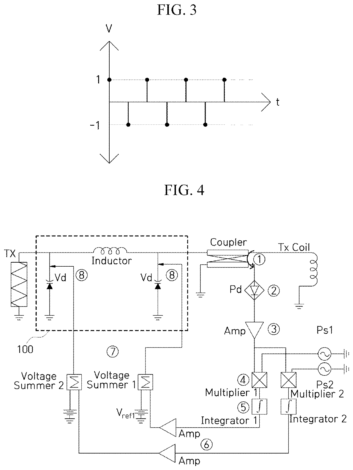
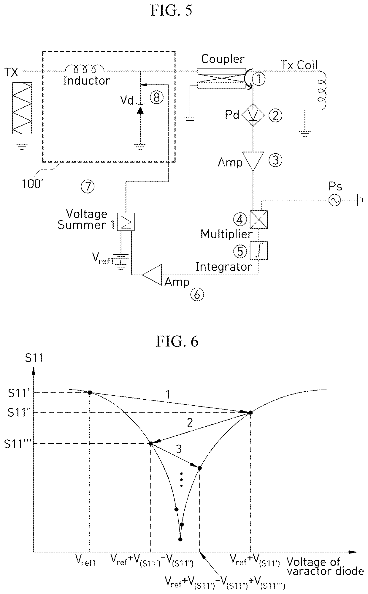
The present invention relates to an apparatus and method capable of performing immediate impedance matching according to changes of a distance and positions between TX / RX coils. The present invention includes: an impedance adjustment unit including a voltage-controlled variable capacitance device; a power detector configured to detect a reflection signal which enters the transmitter or receiver when there is no impedance matching to measure a magnitude of the reflection signal and convert the reflection signal into a DC signal; a multiplier configured to multiply the DC signal with a periodic signal; an integrator configured to accumulate and add a signal in which the DC signal and the periodic signal are multiplied; and a voltage summer configured to sum a signal output from the integrator with a reference voltage to calculate a capacitance control voltage to be applied to the voltage-controlled variable capacitance device.

Description

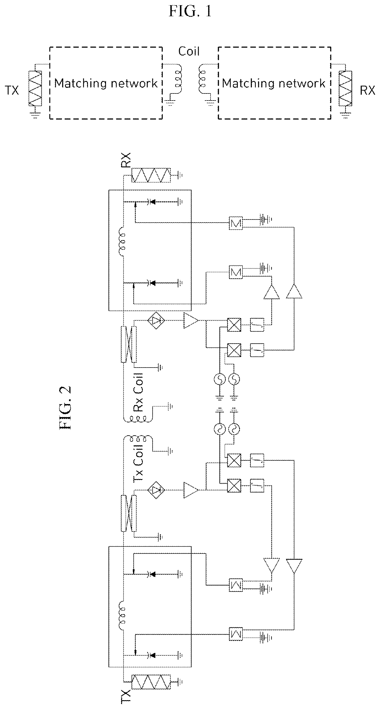
CROSS-REFERENCE TO RELATED APPLICATIONS[0001]This application claims the benefit under 35 U.S.C. § 119(a) of Korean Patent Application No. 10-2020-0175910, filed on Dec. 15, 2020 in the Korean Intellectual Property Office, the entire disclosure of which is incorporated herein by reference for all purposes.BACKGROUND OF THE INVENTION1. Field of the Invention[0002]The present invention relates to a wireless power transfer or wireless charging technology using a magnetic resonance method, and an impedance matching technology between transmitter (TX) and receiver (RX) coils.2. Discussion of Related Art[0003]A magnetic resonance method, which is one of wireless power transfer or wireless charging methods, is a technology for transmitting and receiving energy in a situation in which a transmitter (TX) coil and a receiver (RX) coil are spaced apart from each other as shown in FIG. 1.[0004]Transmission efficiency, which is a core element of wireless charging, greatly varies according to pos...

Claims


Application Information

Patent Timeline
IPC IPC(8): H03H11/28H02J50/12
CPCH03H11/28H02J50/12H03H7/38H03H7/40Y02T10/70Y02T90/14Y02T10/7072H01F38/14
Inventor PARK, JONG HYUK
Owner HYUNDAI MOBIS CO LTD
Learn More