
Crank circular eccentric block transmission structure and compressor

A technology of transmission structure and eccentric block, which is applied in the direction of crank, eccentric wheel, eccentric shaft, etc., can solve the problems of large size and weight of the unit, large vibration and noise of the unit, and unbalanced second-order inertial force, so as to achieve compact structure and reduce vibration and noise , the effect of reducing heat

Pending Publication Date: 2021-08-20
HEFEI GENERAL MACHINERY RES INST
View PDF5 Cites 0 Cited by
  • Summary
  • Abstract
  • Description
  • Claims
  • Application Information

AI Technical Summary

Problems solved by technology

The second-order inertial force in the process of piston movement cannot be balanced, which has the disadvantages of large vibration and noise of the unit, large size and weight of the unit, so it needs to be solved urgently

Method used


Image

  • Crank circular eccentric block transmission structure and compressor
  • Crank circular eccentric block transmission structure and compressor
  • Crank circular eccentric block transmission structure and compressor

Examples


Embodiment Construction

[0034] The following will clearly and completely describe the technical solutions in the embodiments of the present invention with reference to the accompanying drawings in the embodiments of the present invention. Obviously, the described embodiments are only some, not all, embodiments of the present invention. Based on the embodiments of the present invention, all other embodiments obtained by persons of ordinary skill in the art without making creative efforts belong to the protection scope of the present invention.

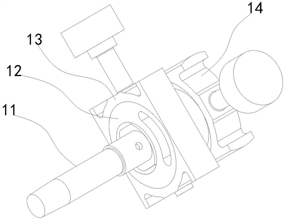
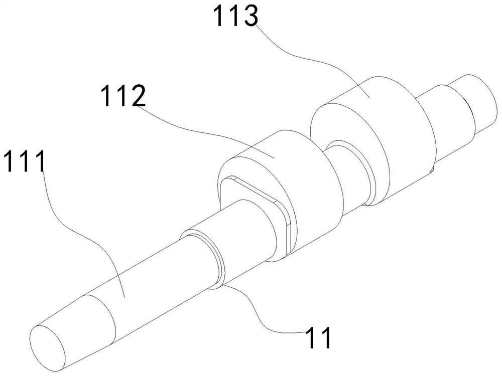
[0035] see Figure 1-12 , in an embodiment of the present invention, a crank circular eccentric block transmission structure includes a crankshaft 11 and a piston part whose action direction is perpendicular to the axis of the crankshaft 11 . The crank shaft 11 includes a central shaft 111 and an inner eccentric part arranged eccentrically on the central shaft 111 , and the inner eccentric part is an eccentric round block fixed on the central shaft 111 .

[0...


PUM


Abstract

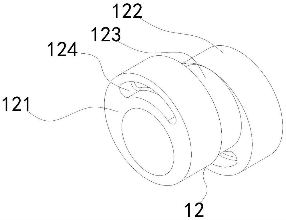
The invention discloses a crank circular eccentric block transmission structure. The crank circular eccentric block transmission structure comprises a crank shaft and a piston part with the action direction perpendicular to the axis of the crank shaft, the crank shaft comprises an inner eccentric part eccentrically arranged on a center shaft of the crank shaft, and the inner eccentric part is sleeved with an outer eccentric part eccentrically matched with the inner eccentric part; a piston of the piston part is connected with a piston connecting section extending out of an air cylinder, and the piston connecting section is matched with the outer eccentric part in a rotating manner; and the eccentric distance between the center shaft and the inner eccentric part is a, the eccentric distance between the inner eccentric part and the outer eccentric part is b, and a is equal to b. According to the crank circular eccentric block transmission structure, a traditional connecting rod structure large in occupied space is replaced, the unit structure is more compact, the occupied space of a compressor unit is reduced, and the weight of the unit is reduced; and the eccentric distance between the center haft and the inner eccentric part is set to be equal to the eccentric distance between the inner eccentric part and the outer eccentric part, so that the motion of the piston is first-order simple harmonic motion, the piston cannot generate second-order inertia force in the motion process, and the vibration noise of the unit is greatly reduced.

Description

technical field [0001] The invention relates to the field of fluid machinery, in particular to a crank circular eccentric block transmission structure and a compressor. Background technique [0002] A reciprocating compressor is a machine that converts the rotary motion of the crankshaft into the reciprocating motion of the piston, and realizes the pressurization and delivery of gas through the periodic change of the cylinder volume. [0003] The conversion process employed by conventional reciprocating compressors primarily uses a crank-and-rod configuration. The reciprocating motion of the piston in the crank-connecting rod structure compressor relies on the rotation of the crankshaft, which drives the connecting rod to perform circular swing, and the circular swing of the connecting rod drives the piston and is realized under the constraint of the cylinder. Since the length of the connecting rod in the crank-link mechanism is greater than the radius of the crank, the cra...

Claims


Application Information

Patent Timeline
Patent Type & Authority Applications(China)
IPC IPC(8): F16H21/50F16C3/12F16C3/22F16C3/14F16C3/18F04B39/00F04B39/02F04B39/12F04B39/06
CPCF16H21/50F16C3/12F16C3/22F16C3/14F16C3/18F04B39/0094F04B39/02F04B39/128F04B39/06F04B39/0027
Inventor 姜慧君李金禄陈德祥韩占华叶鹏
Owner HEFEI GENERAL MACHINERY RES INST
Learn More