
Device for cleaning a tool, in particular a mixer propeller, and associated method

Pending Publication Date: 2022-02-17
NANGUET JACQUES JEAN CLAUDE
View PDF0 Cites 0 Cited by
  • Summary
  • Abstract
  • Description
  • Claims
  • Application Information

AI Technical Summary

Benefits of technology

The invention is a device that makes it easy to clean by spinning its brushing threads and working portion. The even distribution of thread angles around the container's longitudinal axis also improves cleaning efficiency by creating multiple zones for brushing. Its technical effects are quick and thorough cleaning with minimal effort.

Problems solved by technology

If not cleaned early enough, removing solidified debris can cause damage, chipping or breakage, and premature tool wear.
This results in product splashing on the user and considerable cleaning time.

Method used


Image

  • Device for cleaning a tool, in particular a mixer propeller, and associated method
  • Device for cleaning a tool, in particular a mixer propeller, and associated method
  • Device for cleaning a tool, in particular a mixer propeller, and associated method

Examples


Embodiment Construction

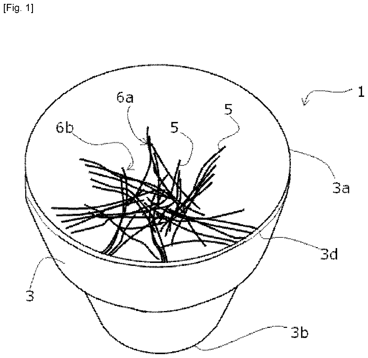
[0031]The invention relates to a cleaning device 1 of tool 2, such as those used in building construction work. The invention is particularly suitable for cleaning tool 2 capable of being driven in rotation. Tool 2 is in particular a mixer.

[0032]The device 1 according to the invention makes it possible to greatly improve the cleaning of tools capable of being driven in rotation, such as a propeller 2a of a mixer 2 comprising residues of sticky materials such as glue.

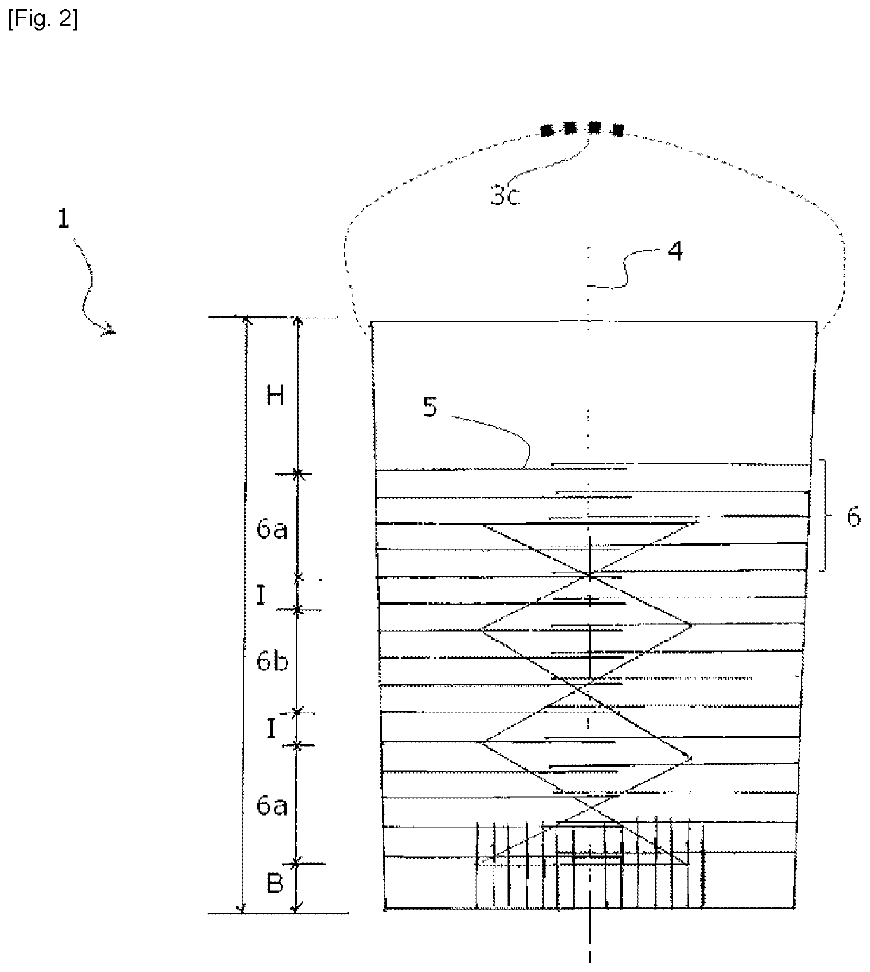
[0033]The cleaning device 1 comprises a container 3. The container 3 is chosen so as to be able to contain the portion of the tool 2 which is to be cleaned. This is in particular a working portion (2a) of a tool to be cleaned.

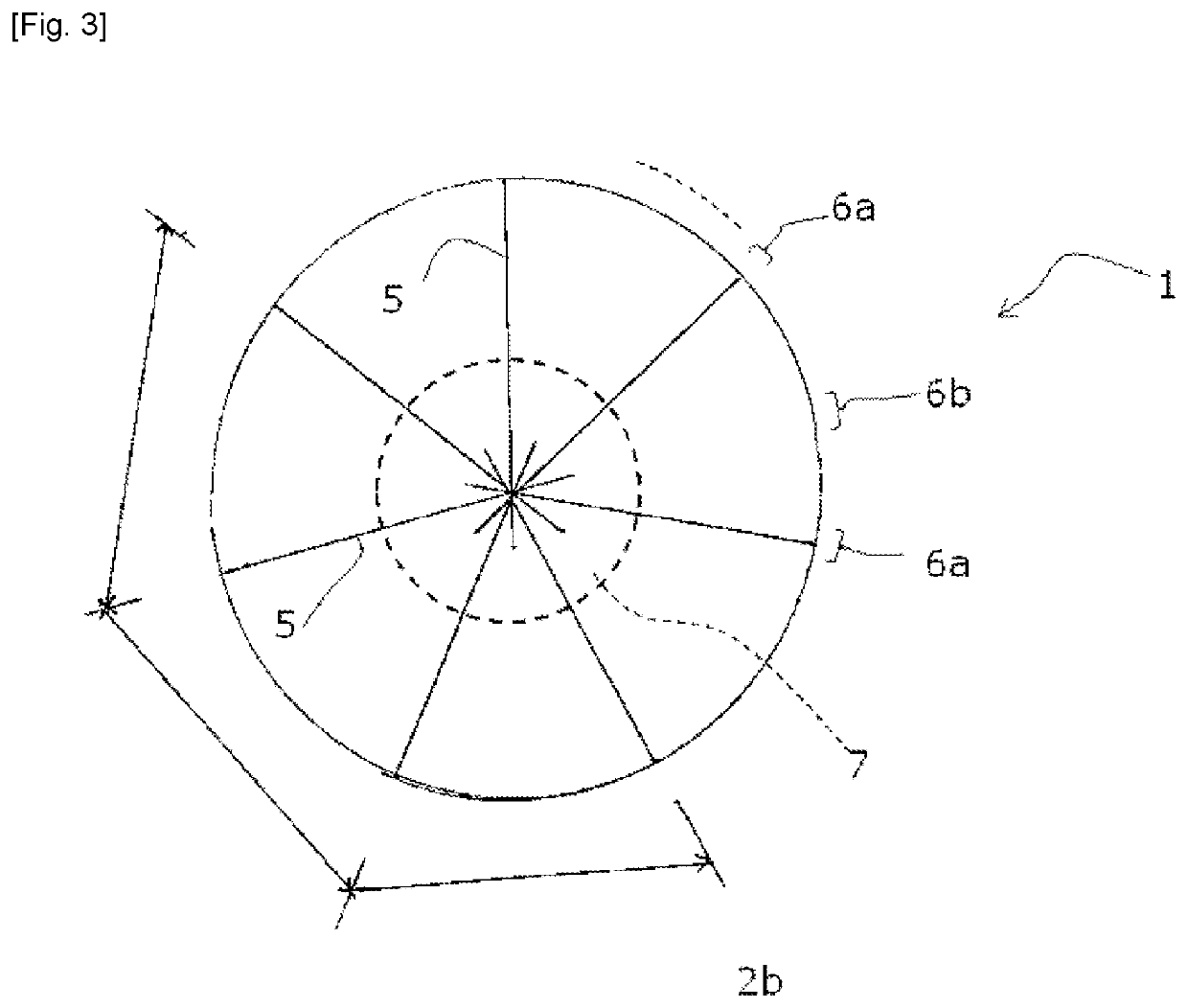
[0034]The container 3 has a longitudinal axis 4. The longitudinal axis 4 extends along the length of the container 3. The longitudinal axis 4 may be central to the container 3.

[0035]Preferably, the container 3 has a prismatic shape, more particularly a cylindrical shape; or a shape of a truncated co...


PUM


Abstract

A device and method for cleaning a tool, in particular a rotatable tool. The device includes a receptacle that has a longitudinal axis and contains at least one work portion of a tool that is to be cleaned; a plurality of brushing threads to be placed in the receptacle such that the threads are not parallel to the longitudinal axis, preferably extending at an angle or substantially perpendicularly to the longitudinal axis, with at least three thread support sections that support the brushing threads and are spaced angularly apart at regular intervals around the longitudinal axis.

Description

TECHNICAL FIELD[0001]The present invention relates to the cleaning of tools, in particular those used in building construction work interallia. Particularly, the invention relates to a device for cleaning a tool, more particularly a tool capable of being driven in rotation, such as a mixer propeller. The invention further relates to a corresponding cleaning method.BACKGROUND[0002]In the aforementioned field, it is common to use products which have to be dissolved and mixed, such as glue. Specific devices, known as mixers or kneaders, have therefore been provided, comprising a rotor, an arm and a propeller which, when rotating, makes it possible to mix the products necessary for the work. Propellers having complex shapes including convolutions are generally used.[0003]As a result of these mixtures, product residues stick to the propeller and solidify.[0004]If not cleaned early enough, removing solidified debris can cause damage, chipping or breakage, and premature tool wear.[0005]It ...

Claims


Application Information

Patent Timeline
IPC IPC(8): B01F15/00A46B9/02
CPCB01F15/00045A46B2200/3006A46B9/028B01F15/00025B08B1/00B08B3/102B01F35/1452B01F35/121B08B1/12
Inventor NANGUET, JACQUES JEAN CLAUDE
Owner NANGUET JACQUES JEAN CLAUDE
Learn More