
Spray washer structure of insulator used for aircraft

Inactive Publication Date: 2006-10-26
EMERALD PACIFIC AIRLINES
View PDF6 Cites 13 Cited by
  • Summary
  • Abstract
  • Description
  • Claims
  • Application Information

AI Technical Summary

Benefits of technology

[0009] The primary objective of the invention is to provide a spray washer structure of insulator used for aircraft that is capable of adequately adjusting the direction of the nozzle according to the need by pivotally rotating the nozzle to facilitate the cleaning of the insulators that are disposed in different direction, thereby, to improve the cleaning efficiency and lower the operating cost.
[0010] The secondary objective of the invention is to provide a spray washer structure of insulator used for aircraft that is stable in positioning and is capable of effectively preventing the inner tube from being moving upward to touch the rotor of the helicopter, thereby, is safe in operation.

Problems solved by technology

However, the insulators needs to be cleaned periodically since the insulated function of the insulators tends to deteriorate due to their long-time exposure in the open space and their having dust adhered and foreign substance intruded.
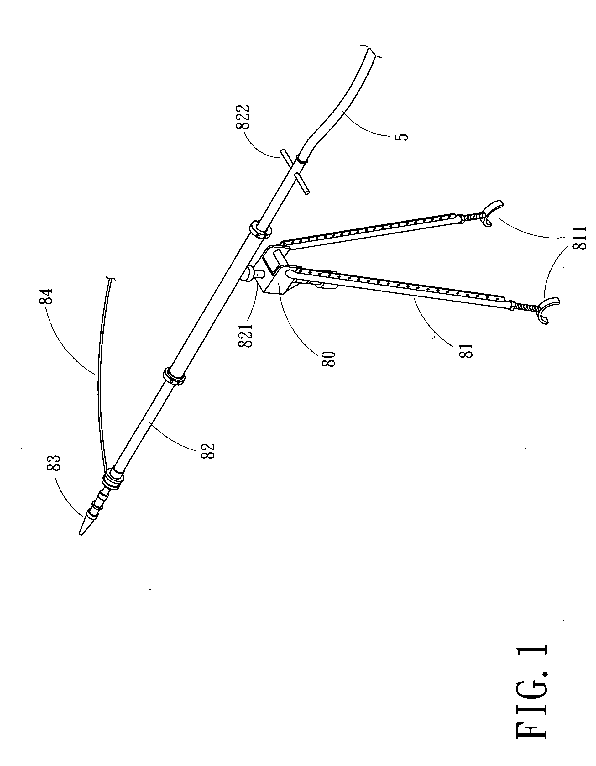
Nevertheless, as the tower of high-voltage power-transmission-line is generally too high to be reached for the operator to clean by the use of spray washer from the ground, aircraft such as helicopter is usually employed to clean the insulators FIG. 1 is a pictorial views of the spray washer structure of insulator of the prior art.
Consequently, the spray washing operation is energy and time-consuming, and will seriously affect the efficiency and quality of insulator cleaning.

Method used


Image

  • Spray washer structure of insulator used for aircraft
  • Spray washer structure of insulator used for aircraft
  • Spray washer structure of insulator used for aircraft

Examples


Embodiment Construction

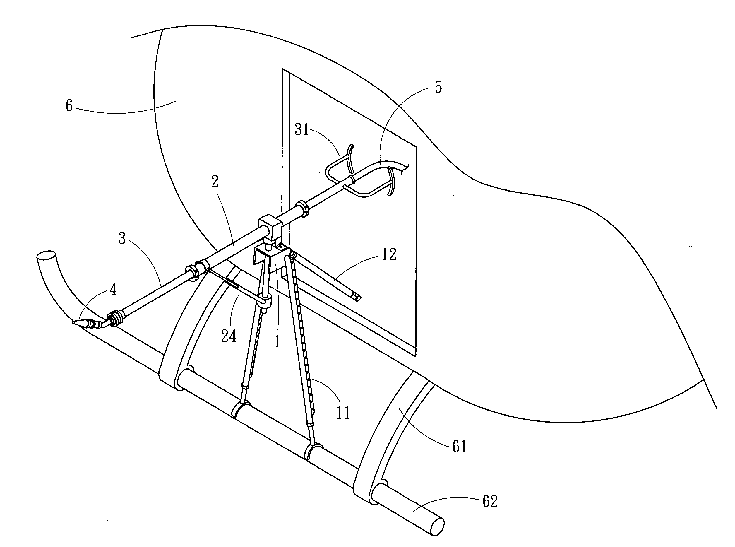
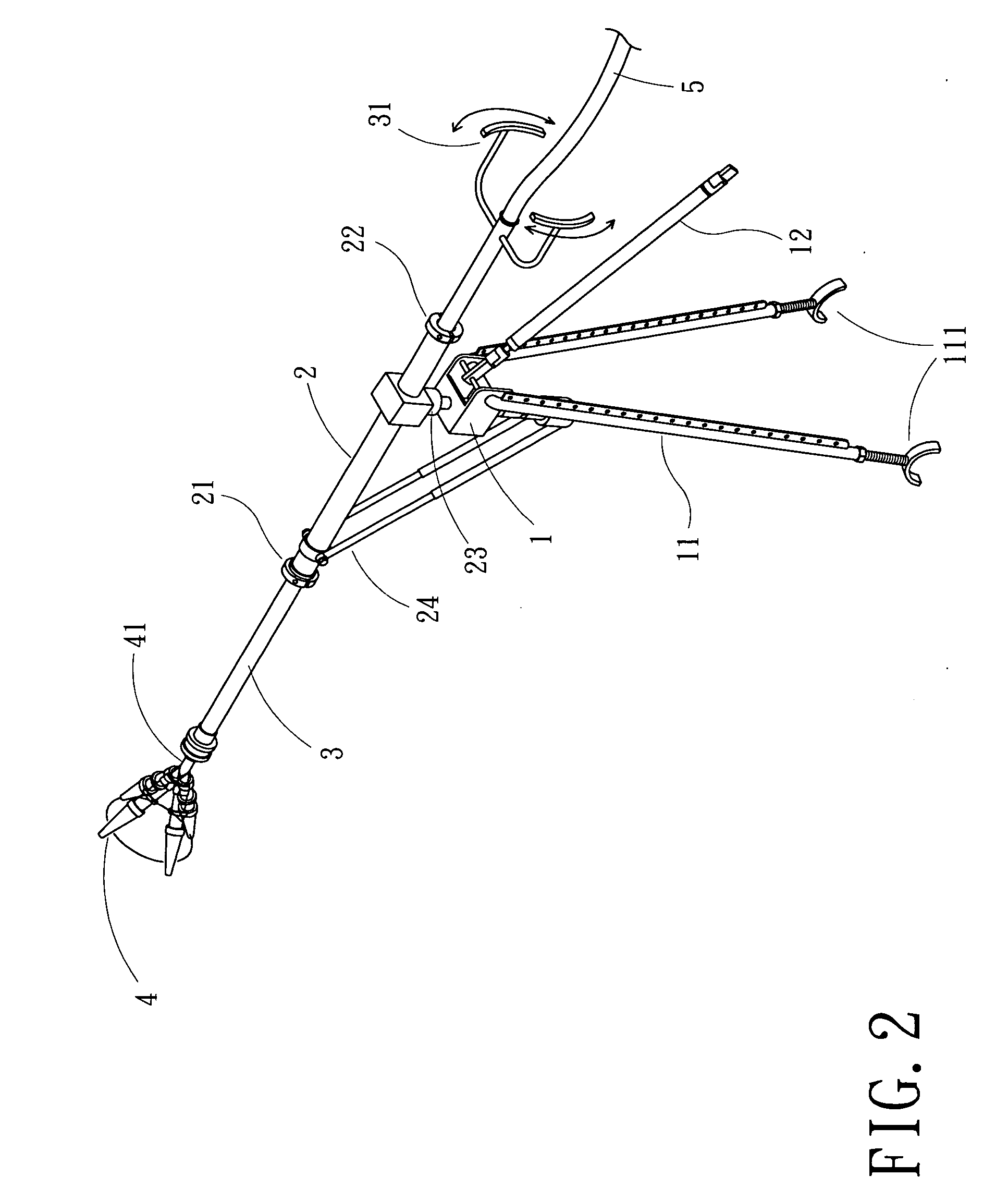
[0017]FIG. 2 is a pictorial schematic view of the main structure of the invention and FIG. 3 is a pictorial schematic view showing the assembled structure when the invention is mounted at the aircraft. As shown in FIG. 2 and FIG. 3, the spray washer structure of the invention includes a pivot seat (1), a core tube (2), an inner tube (3), and a nozzle (4). The bottom end of the pivot seat (1) provides a plurality of legs (11) and a rear leg (12). The legs (11) have hook-talons (111) at their bottom ends for hooking at the bottom cross-bar (62) of the landing skids (61) of an aircraft (such as a helicopter) (6). Moreover, the rear leg (12) can stretch through the hatch of the aircraft (such as a helicopter) into the cabin to reach its floor to form a stable multiple-point support.

[0018] The mid-section of the core tube (2) is pivotally connected to the pivot seat (1) through a pivot (23) provided thereat. Moreover, pivoted socket seats (21), (22) are provided respectively at both end...


PUM


Abstract

A spray washer structure of insulator used for aircraft includes a pivot seat, a core tube, an inner tube, and a nozzle. The pivot seat is supported by a plurality of legs and a rear leg that are attached at the aircraft. The mid-section of the core tube is pivotally connected to the pivot seat by the use of a pivot, and an end portion of the core tube is connected to at least an inclined resilient buffer link at another end portion of the pivot. The inner tube being passed through and secured in the core tube in pivotally connected status is capable of facilitating the operation of controlling the pivoting rotation therein. The nozzle is secured at the front end of the inner tube by a pivotal joint which is bent and inclined as well as stretchy and rotatory. Moreover, the nozzle is also connected to a hose inserting from the front end of the inner tube and passing through it to be exposed at the rear end thereof to be connected to a water source that is provided beforehand. By the use of the pivoted inner tube in association with the bent and inclined as well as stretchy and rotatory joint, the nozzle is capable of forming various orientation in different directions to fit for the insulators having different arrangement and built-up directions.

Description

BACKGROUND OF THE INVENTION [0001] 1. Field of the Invention [0002] The invention relates to a spray washer structure of insulator used for aircraft, and more particularly, to a spray washer structure of insulator used for aircraft that can steadily position, can be handy to operate, and can pivotally rotate the direction of the spray nozzle to facilitate the washing of the insulator. [0003] 2. Description of the Prior Art [0004] Insulators that are equipped at the tower of high-voltage power-transmission-line and are used for insulation between the transmission-line and tower are very important components for the safety and security of facilities and people. However, the insulators needs to be cleaned periodically since the insulated function of the insulators tends to deteriorate due to their long-time exposure in the open space and their having dust adhered and foreign substance intruded. Nevertheless, as the tower of high-voltage power-transmission-line is generally too high to ...

Claims


Application Information

Patent Timeline
IPC IPC(8): B64D1/18B05B1/00B05B15/68B64D1/22
CPCB08B3/026B08B3/028B05B15/061B05B9/01B64D1/22B05B15/62B05B15/63
Inventor LEE, JAMES
Owner EMERALD PACIFIC AIRLINES
Learn More