

Power delivery control and over current protection
a power supply and current protection technology, applied in the direction of electric variable regulation, process and machine control, instruments, etc., can solve the problems of load, damage to circuit wiring, and certain conventional circuits are susceptible to damage, and achieve the effect of reducing or eliminating the delivery of current through load
- Summary
- Abstract
- Description
- Claims
- Application Information
AI Technical Summary
Benefits of technology
Problems solved by technology
Method used
Image

Examples
Embodiment Construction
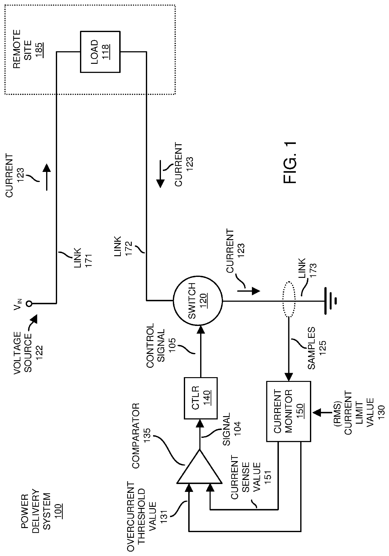
[0036]Embodiments herein include an apparatus comprising a switch, a current monitor, and a controller. During operation, the switch controls an amount of current through the load. The current monitor samples a magnitude of the current through the load, a magnitude of which varies over time during a time duration. Based on integrating the sample magnitudes of the current through the load over the time duration, the current monitor produces a current sense value. The current sense value is representative of an amount of current through the load. The controller controls an operational state of the switch based upon a comparison of the current sense value with respect to an over-current threshold value. For example, in response to detecting a condition in which the current sense value is greater than the overcurrent threshold value, the controller turns OFF (deactivates) the switch, reducing or eliminating delivery of current through the load.
[0037]Now, more specifically, FIG. 1 is an ...
PUM
 Abstract
Description
Claims
Application Information