Resistive load bank systems

a load bank and load technology, applied in the direction of electric generator control, generation protection through control, cooling/ventilation arrangement, etc., can solve the problems of diesel engine coupled to a generator, diesel engine susceptible to wet stacking, risk of wet stacking, etc., to reduce load or eliminate the problem of loading

Pending Publication Date: 2022-08-25
ALLIANCE NORTH AMERICA INC
View PDF5 Cites 0 Cited by
  • Summary
  • Abstract
  • Description
  • Claims
  • Application Information

AI Technical Summary

Benefits of technology

[0004]Embodiments of the present invention provide a system for managing an operational environment of a diesel engine driven generator. A load bank system provides for the elimination or reduction of loading issues on diesel engine driven generators. The load bank system includes a resistive load bank that provides a dummy load for the generator to ensure that the diesel engine is run with a sufficient load to ensure that the diesel engine is running at an optimum operating temperature, such that the diesel engine avoids wet stacking conditions. The resistive load bank includes a plurality of resistors in a configurable arrangement. The load bank system includes a load bank controller for configuring the plurality of resistors such that the resistive load bank provides a desired load percentage regardless of the voltage output of the generator.

Problems solved by technology

While a diesel engine provides an efficient driver for a generator, diesel engines are susceptible to wet stacking (i.e., when unburnt diesel fuel passes into the diesel exhaust system and produces an oily residue).
For example, a diesel engine coupled to a generator is susceptible to wet stacking when the generator it is driving has no load or only a minimal load coupled to it.
When the generator is operating with no load or only a minimal load, the diesel engine is likely only idling, resulting in the risk of wet stacking because the diesel engine is not at a proper operating temperature (allowing unburnt fuel to escape into the diesel exhaust system).

Method used


Image

  • Resistive load bank systems
  • Resistive load bank systems
  • Resistive load bank systems

Examples


Embodiment Construction

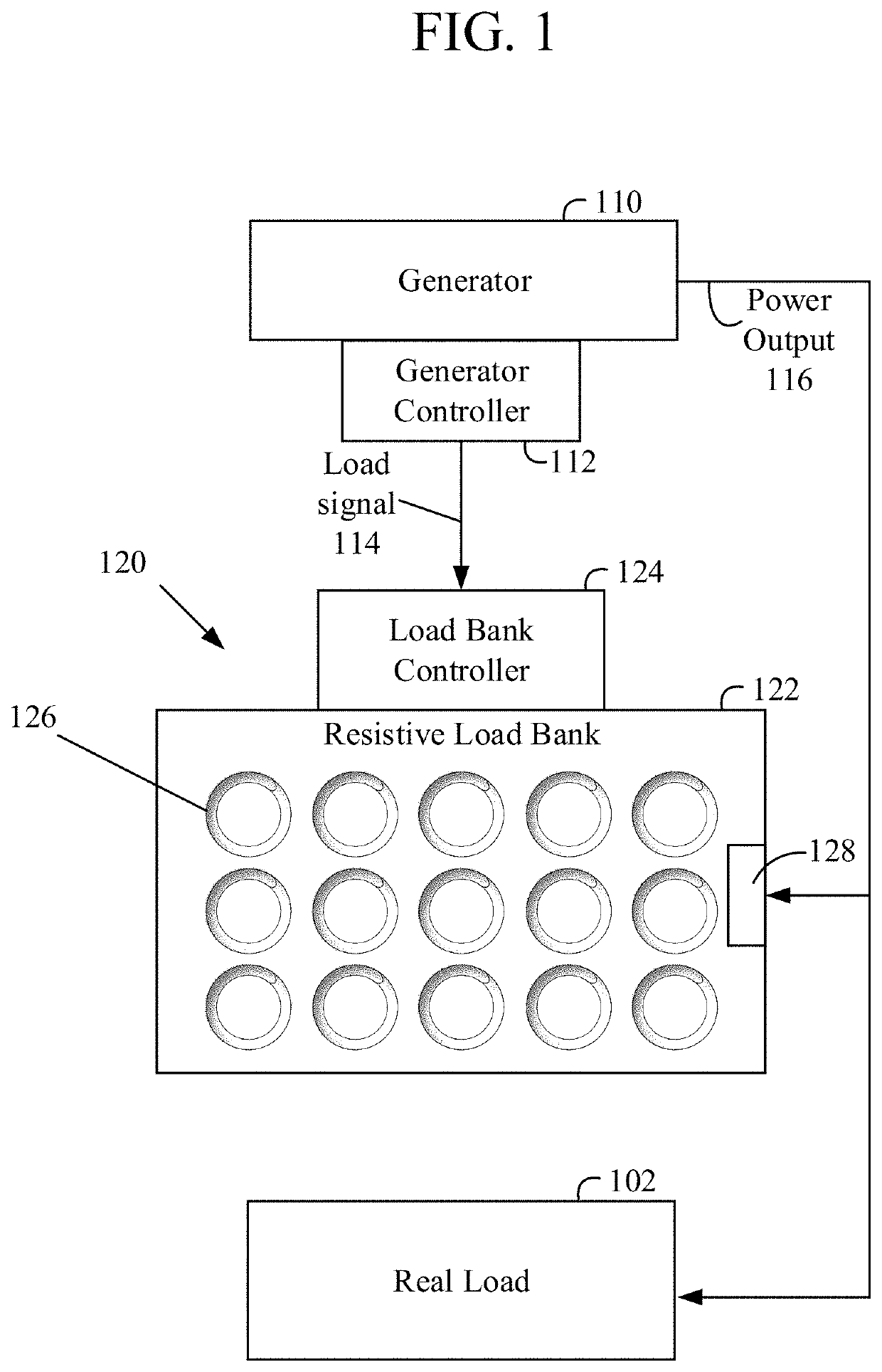
[0025]Referring to the drawings and the illustrative embodiments depicted therein, a load bank system provides for the elimination or reduction of loading issues on diesel engine driven generators, such as, for example, EPA Tier 4F certified or compliant diesel engine driven mobile generators. Exemplary load bank systems may be assembled or fitted to portable prime power skid generators or trailer-mounted diesel generators and provide selective engagement of resistive load banks to provide “dummy loads” to their respective generators when a real load is below a threshold load value. Alternatively, the load bank systems may be arranged within a housing of the generator.

[0026]FIG. 1 illustrates a load bank system 120 that includes a resistive load bank 122 that absorbs energy from a diesel generator assembly 110 and allows the generator 110 to work under a loaded condition (even when there is no load or only a minimal load coupled to the generator 110) that is sufficient to prevent we...


PUM


Abstract

A load bank system is configured for providing a minimum load for a generator. The load bank system includes a resistive load bank, a relay, and a load bank controller. The resistive load bank is configured to provide a resistive load to a generator. The relay is configured to selectively engage the resistive load of the resistive load bank to the generator. The load bank controller is operable to control the relay such that the resistive load is engaged when a real load coupled to the generator is below a threshold load value. The load bank system may be arranged within a housing of the generator.

Description

CROSS REFERENCE TO RELATED APPLICATIONS[0001]The present application claims the filing benefits of U.S. provisional application, Ser. No. 63 / 147,848, filed Feb. 10, 2021, which is hereby incorporated by reference herein in its entirety.FIELD OF THE INVENTION[0002]The present invention is directed to load bank systems, and in particular to load bank systems for generators.BACKGROUND OF THE INVENTION[0003]Generators are often driven by diesel engines. While a diesel engine provides an efficient driver for a generator, diesel engines are susceptible to wet stacking (i.e., when unburnt diesel fuel passes into the diesel exhaust system and produces an oily residue). Wet stacking happens when a diesel engine is running at a low percentage or proportion of its capacity. For example, a diesel engine coupled to a generator is susceptible to wet stacking when the generator it is driving has no load or only a minimal load coupled to it. When the generator is operating with no load or only a mi...

Claims


Application Information

Patent Timeline
Patent Type & Authority Applications(United States)
IPC IPC(8): H02P9/00H02K9/14H02K11/00
CPCH02P9/006H02K9/14H02K11/0094H02K2213/06H02K11/26H02K9/04
Inventor NORRIS, JOSEPHHARRIS, JACKCATERINA, THOMAS J.
Owner ALLIANCE NORTH AMERICA INC
Why Eureka
Try Eureka