
An insufflator for exposing structures within an internal body cavity

an insufflator and internal cavity technology, applied in the field of insufflators for exposing structures within the internal cavity, can solve the problems of limited changes in insufflation pressure, difficult maintenance of surgical workspace, and inability to maintain the insufflator, so as to reduce the uptake of co2, reduce the applied co2 pressure, and improve the operation of the insufflator

Pending Publication Date: 2022-02-24
ERASMUS UNIV MEDICAL CENT ROTTERDAM ERASMUS MC +1
View PDF0 Cites 2 Cited by
  • Summary
  • Abstract
  • Description
  • Claims
  • Application Information

AI Technical Summary

Benefits of technology

The invention aims to reduce stress on the body during endoscopy and endoscopic surgery procedures by optimizing the pressure and space created by insufflation. The force of oscillation needed to probe the mechanical properties of the cavity can be applied by means of an insufflator, which can measure the physical properties of the internal cavity such as tissue reactance. This allows for the optimization of gas insufflation pressure and reduces the risk of excessive stress on the body.

Problems solved by technology

Manual insufflation of gas into the internal cavity can make the surgical workspace quite difficult to maintain.
Limited changes to the insufflation pressure are made when the achieved gas volume does not provide sufficient view or space to perform a procedure in.
Applying generalized standard pressure settings often leads to either too little or too much pressure being applied to the tissues surrounding the cavity.
For example, in abdominal surgery the gas pressure needed for performing minimally invasive surgery creates upward pressure on the diaphragm, hampering ventilation.
In patients that are difficult to ventilate (e.g. young children and the obese) the unnecessary application of too much insufflation pressure therefore hampers the ability to ventilate the patient properly.

Method used


Image

  • An insufflator for exposing structures within an internal body cavity
  • An insufflator for exposing structures within an internal body cavity
  • An insufflator for exposing structures within an internal body cavity

Examples


Embodiment Construction

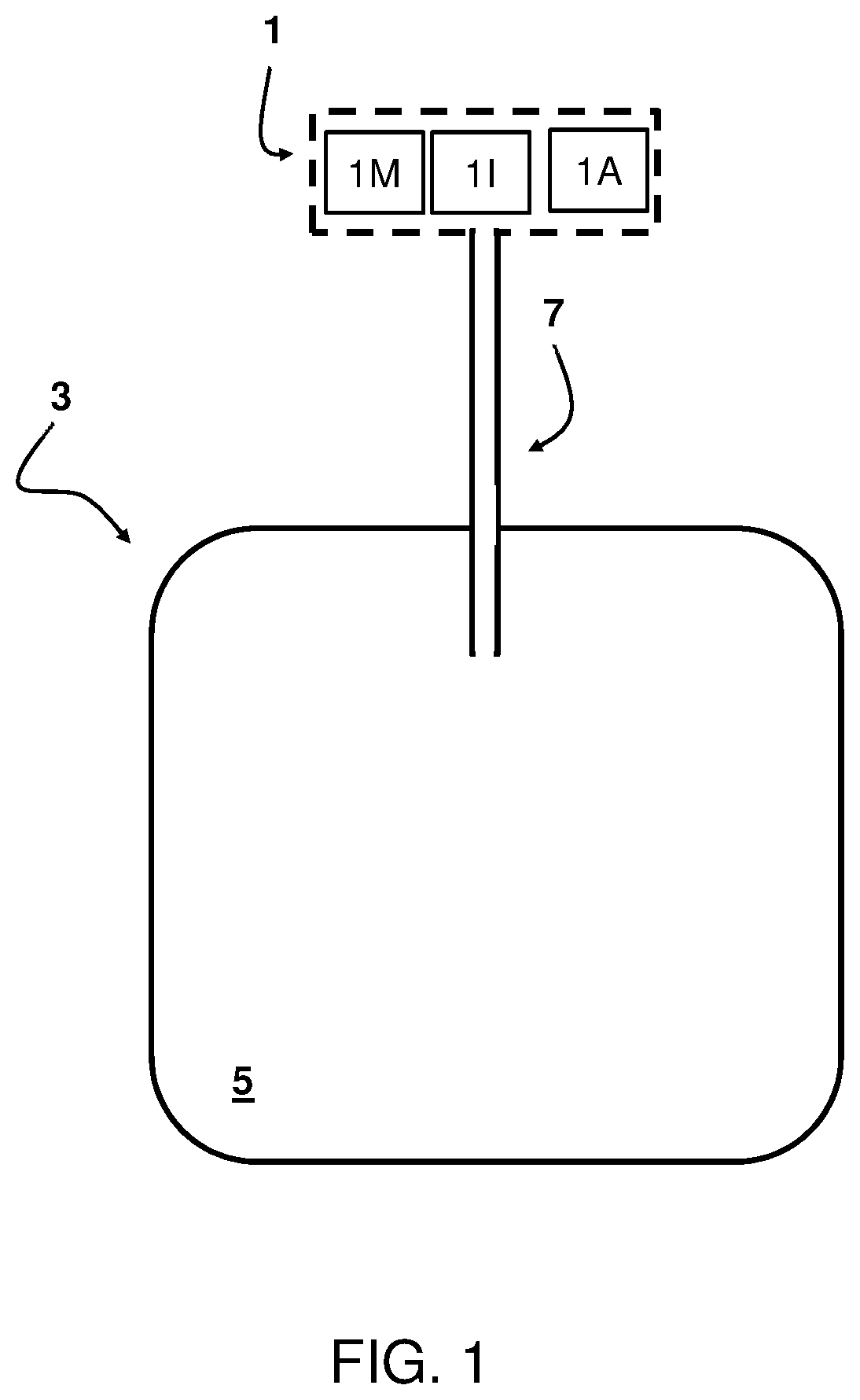
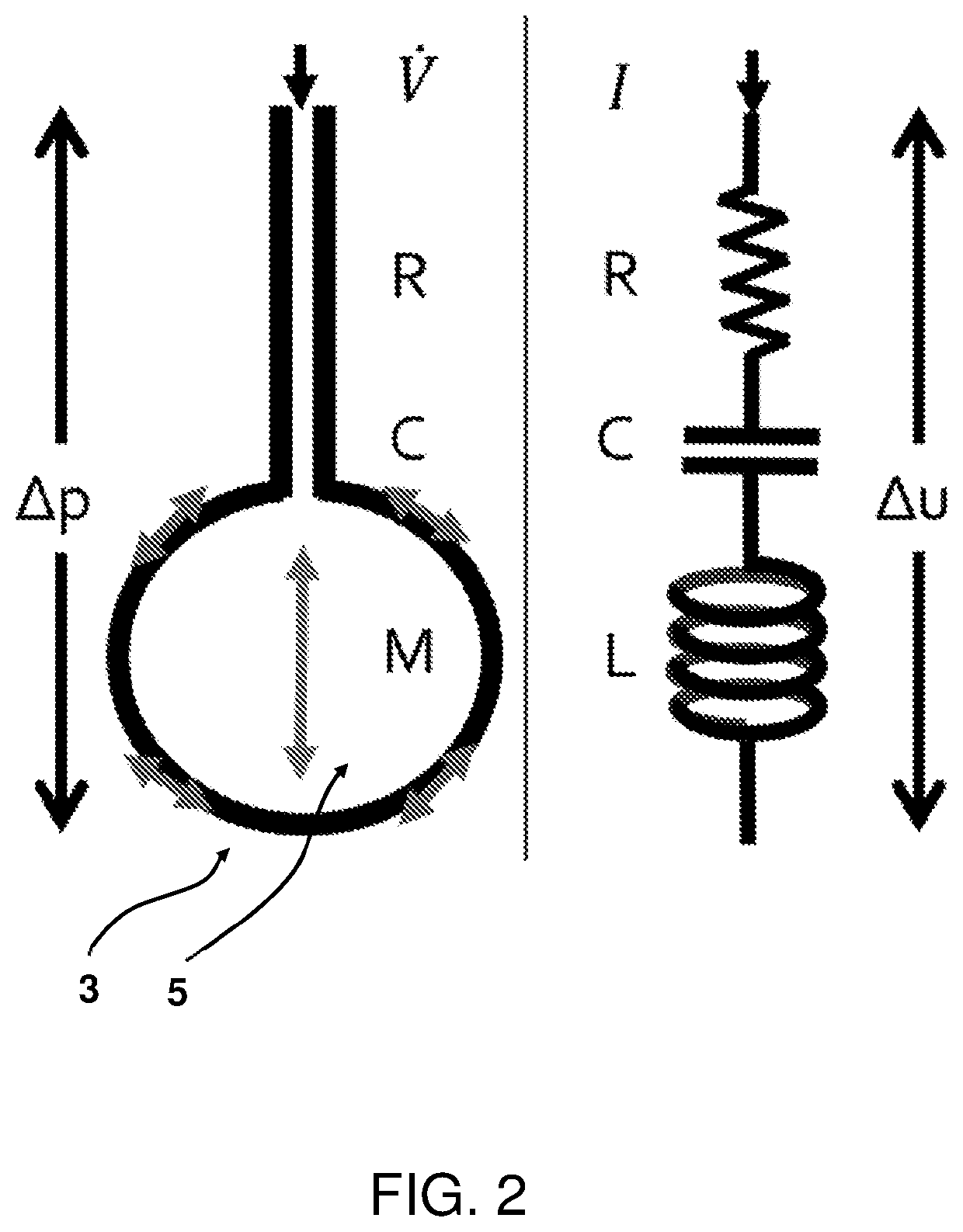
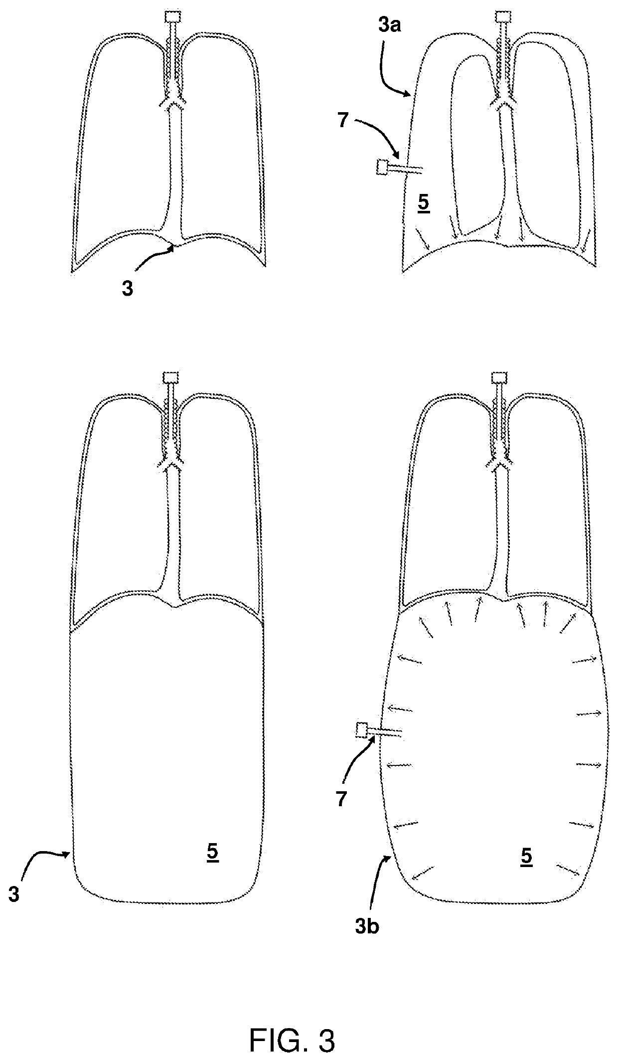
[0081]FIG. 1 shows a schematic diagram of an apparatus 1 used for insufflation of an internal cavity 3. The apparatus 1 is arranged for exposing structures (e.g. organs) within the internal cavity 3 of a human body for diagnostic and / or therapeutic endoscopic procedure. The internal cavity 3 forms a confined volume 5 within the human body. The apparatus 1 comprises an input conduit 7 for exchanging gas with the confined volume 5. The apparatus 1 further comprises a gas insufflator 1I for insufflation of gas into the confined volume through the input conduit, wherein the gas insufflator 1I is configured to deliver a pressure to the confined volume 5, wherein the gas insufflator is configured to impose at least one pressure or flow oscillation to obtain a forced oscillating pressure or flow delivered to the confined volume, the forced oscillating pressure or flow having at least one preset component with a frequency and an amplitude. Through the input conduit 7, which can be brought i...


PUM


Abstract

An insufflator for exposing structures within an internal cavity forming a confined volume within an animal or human body, the apparatus including: an input conduit for exchanging gas with the confined volume; a gas insufflator for insufflation of gas into the confined volume through the input conduit, wherein the gas insufflator is configured to deliver an insufflator pressure to the confined volume, wherein the gas insufflator is configured to (super)impose at least one pressure or flow oscillation to obtain a forced oscillating pressure or flow delivered to the confined volume, the forced oscillating pressure or flow having at least one component with a frequency and an amplitude; a monitoring unit for monitoring a response of the internal cavity to the forced oscillating pressure or flow for determining one or more physical properties of the internal cavity; and an adapter unit for adjusting the insufflation pressure based on the determined one or more physical properties of the internal cavity.

Description

FIELD OF THE INVENTION[0001]The invention relates to an apparatus for exposing structures within an internal cavity of an animal or human body for diagnostic and / or therapeutic endoscopic procedure. Further, the invention relates to a method of controlling an apparatus for exposing structures within an internal cavity of an animal / human body for a diagnostic and / or therapeutic endoscopic procedure.BACKGROUND TO THE INVENTION[0002]An insufflation apparatus is used for exposing structures within a cavity of an animal / human body, by insufflating gas into that body cavity, in order to obtain a field of vision, through the endoscope, to perform a diagnostic and / or therapeutic endoscopic procedure to one or more of the structures in the body cavity.[0003]The insufflation apparatus can be used in minimal access surgery, allowing surgery through a few small incisions by introduction of a camera and instruments in the internal body cavity. The body cavity can be pressurized and workspace can...

Claims


Application Information

Patent Timeline
Patent Type & Authority Applications(United States)
IPC IPC(8): A61M13/00
CPCA61M13/003A61M2205/3344A61M2230/42A61M2205/3334A61M2205/3327A61M13/00A61M16/024
Inventor STERKE, FRANKVAN WETERINGEN, WILLEMVLOT, JOHNNYGOOS, TOMAS GIJSBERTUSDELLACA, RAFFAELE LORENZOMILESI, ILARIA
Owner ERASMUS UNIV MEDICAL CENT ROTTERDAM ERASMUS MC
Learn More