Supercharge Your Innovation With Domain-Expert AI Agents!

Panels for obstructing air flow through apertures in an aircraft wing

a technology of apertures and obstructing air flow, which is applied in the direction of wing lift, de-icing equipment, wing skin, etc., can solve the problem of unsatisfactory flow characteristics

Active Publication Date: 2022-02-24
BOMBARDIER INC
View PDF2 Cites 0 Cited by
  • Summary
  • Abstract
  • Description
  • Claims
  • Application Information

AI Technical Summary

Benefits of technology

This solution improves aerodynamic efficiency by reducing leakage flow through the apertures, enhancing lift and reducing loss associated with undesirable flow separation.

Problems solved by technology

The air passages provided by such apertures in the wing skin can lead to undesirable flow characteristics around the wing leading edge region due to leakage flow through the apertures from the high pressure lower wing surface to the low pressure upper wing surface.

Method used


Image

  • Panels for obstructing air flow through apertures in an aircraft wing
  • Panels for obstructing air flow through apertures in an aircraft wing
  • Panels for obstructing air flow through apertures in an aircraft wing

Examples


Embodiment Construction

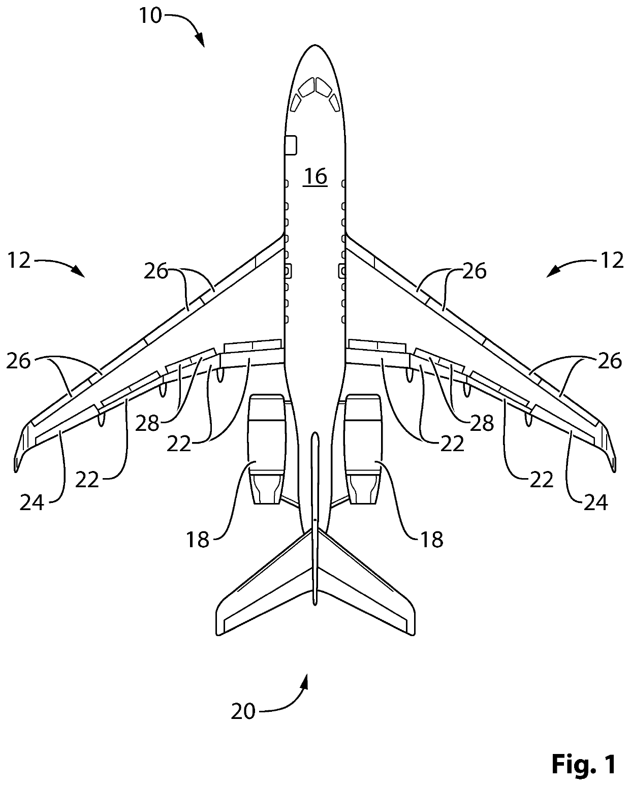
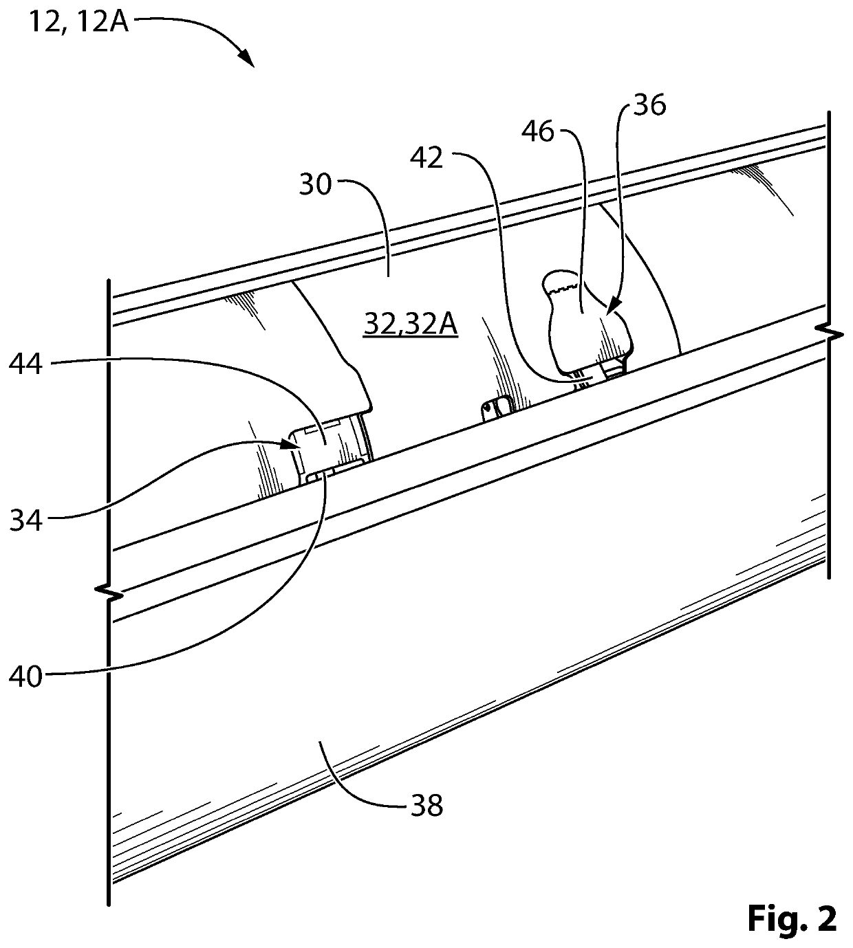
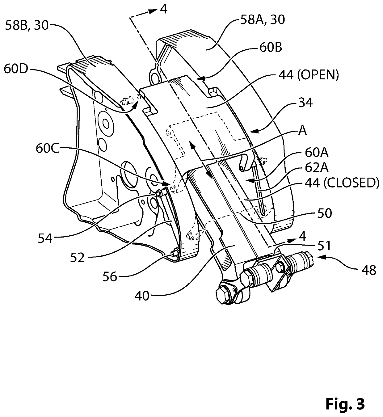
[0075]The present disclosure relates to apparatus for obstructing air flow through apertures in aircraft wing skins where movable members such as slat tracks or anti-icing ducts extend through such apertures. Also disclosed are aircraft wings comprising such apparatus. In some embodiments, the apparatus for obstructing air flow disclosed herein may, for example, be used in conjunction with anti-icing ducts that serve to deliver hot air to leading edge slats or other deployable aerodynamic devices of aircraft. In some embodiments, the apparatus for obstructing air flow disclosed herein may, for example, be used in conjunction with tracks that are part of actuation mechanisms that serve to direct the deployment and retraction of leading edge slats or other deployable aerodynamic devices of aircraft.

[0076]In some embodiments, the apparatus disclosed herein may improve flow characteristics around a wing of an aircraft and consequently improve the aerodynamic efficiency of the wing. For ...


PUM


Abstract

Apparatus for improving flow characteristics around aircraft wings by obstructing air flow through an aperture formed in a wing skin for a movable duct or track are disclosed. In one embodiment, the apparatus comprises a substantially rigid panel movable at least partially across the aperture for at least partially occluding the aperture and for accommodating movement of a slat track extending through the aperture. In another embodiment, the apparatus comprises a hinged panel configured to swing outwardly from an outer side of the wing skin toward an open position to accommodate movement of an anti-icing duct extending through the aperture and to swing toward a closed position at least partially occluding the aperture.

Description

CROSS-REFERENCE TO RELATED APPLICATION(S)[0001]This International PCT Patent Application relies for priority on U.S. Provisional Patent Application Ser. No. 62 / 351,555 filed on Jun. 17, 2016, the entire content of which is incorporated herein by reference.TECHNICAL FIELD[0002]The disclosure relates generally to improving air flow characteristics around aircraft wings and, more particularly, to obstructing air flow through an aperture formed in a wing skin for a movable duct or track.BACKGROUND OF THE ART[0003]Fixed-wing aircraft typically have deployable high lift devices such as trailing edge flaps and leading edge slats that are used to increase the lift coefficient of the wing for take-off and landing. Some fixed-wing aircraft also have ice protection systems that are designed to prevent ice from accumulating on aerodynamic surfaces during flight. Such ice protection systems can include anti-icing systems such as bleed air systems that are intended to keep aerodynamic surfaces ab...

Claims


Application Information

Patent Timeline
Patent Type & Authority Applications(United States)
IPC IPC(8): B64C3/26B64C9/02B64D15/04B64C9/14B64C7/00
CPCB64C3/26B64C9/02Y02T50/30B64C9/14B64C7/00B64D15/04
Inventor POLONI, MATTHEWLARDY, JULIENMASSEY, JEFFREYJASEM, FARIS
Owner BOMBARDIER INC
Features
  • R&D
  • Intellectual Property
  • Life Sciences
  • Materials
  • Tech Scout
  • Unparalleled Data Quality
  • Higher Quality Content
  • 60% Fewer Hallucinations
Learn More