Terminal Antenna Architecture

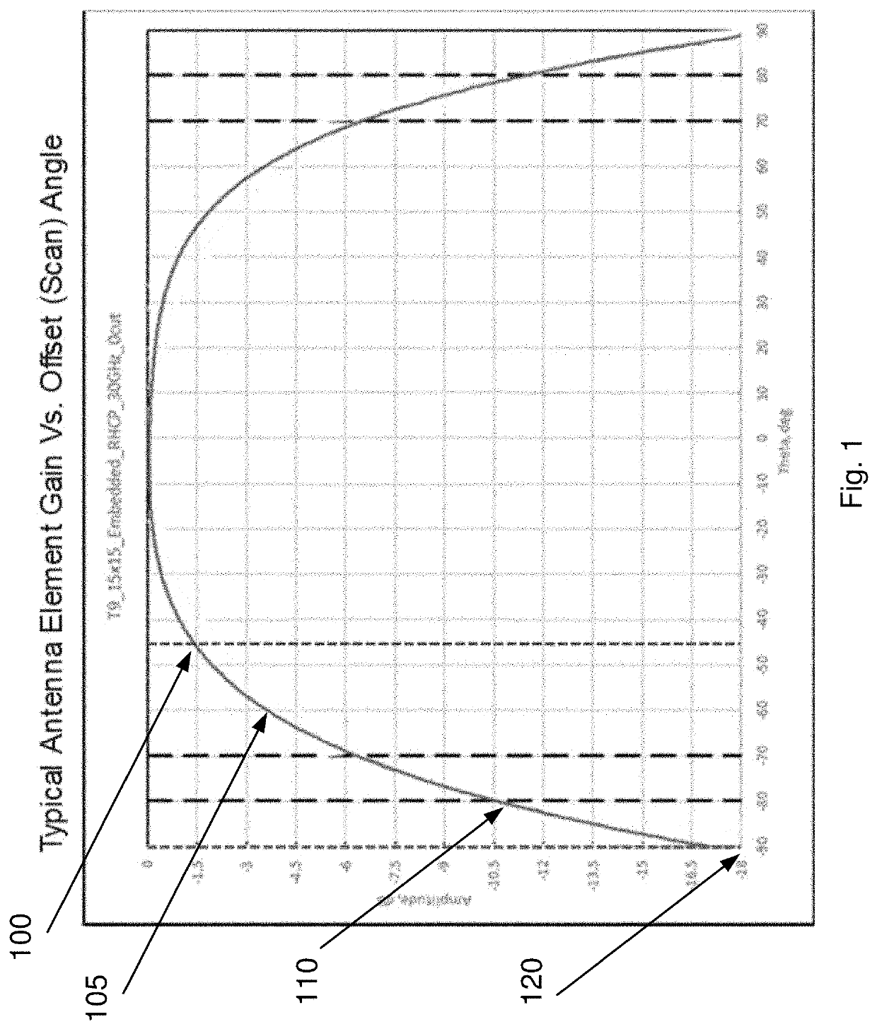
a terminal antenna and antenna technology, applied in the direction of antennas, antenna details, antenna adaptation in movable bodies, etc., can solve the problems of affecting the terminal operation, the antenna has no gain to support satellite link connectivity, and the planar phased array antenna is susceptible to “scan loss”, so as to reduce the loss of scan, the effect of reducing the size and high power consumption

Active Publication Date: 2022-03-17
GILAT SATELLITE NETWORKS
View PDF9 Cites 0 Cited by
  • Summary
  • Abstract
  • Description
  • Claims
  • Application Information

AI Technical Summary

Benefits of technology

[0009]The proposed ‘3SA’ (three-ESA) terminal architecture significantly reduces the above described problems introduced by low elevation angle operation (which is driving traditional terminal design outcome to large receive (Rx) and transmit (Tx) array antennas) both in terms of size (footprint) and in terms of the resulting power consumption. The 3SA terminal architecture is based on separation of the antenna into two orientations: a horizontal orientation for operation at high elevation angles and a vertical orientation for operation at low elevation angles. With the 3SA architecture, the scan loss is kept at relatively low values by switching between the antenna arrays according to various decision parameters, such as an elevation angle between the operational antenna and the satellite. Thus, implementation of the 3SA architecture may result in low gain loss. Consequently, the resulting antenna design may include much smaller arrays, consuming a fraction of the power compared to traditional antenna designs. An antenna controller may switch the antenna operation between one or more vertical Tx / Rx arrays and a horizontal Tx / Rx array, e.g., as function of various input parameters including the elevation angle (that may be calculated based on the aircraft platform (terminal) location and the satellite orbital location).
[0012]Switching (e.g., instantaneous switching) between the antennas assures continuous communication and operation with the satellite, as well as the ability to operate from 90 degrees elevation (using the horizontally oriented antenna on the fuselage) down to 0 degrees elevation (using one of two back-to-back antennas installed inside the aircraft's tail or “dorsal fin”).
[0013]The antenna architectures and implementations described herein may solve the fundamental limitation of planar electronically steered antennas operating at low elevation angles and are especially applicable to aero antennas installed on aircraft traveling at northern (southern) routes while operating with GEO or MEO satellites. The terminal architecture may be similarly applicable to other vertical markets, such as maritime and land mobility, where a flat horizontal antenna design may result in large dimension and high-power consumption, while operating at low elevation angles towards the satellite.
[0014]It may be noted that the same advantage applies when operating with low earth orbit (LEO) satellite constellations, where satellite selection may be done based on criteria of minimal elevation angle towards the vertical or the horizontal antenna arrays, reducing scan loss and maximizing transmit and receive gain values, which corresponds to higher satellite bandwidth utilization and / or user throughput in terms of data rates.

Problems solved by technology

It has been found that planar phased array antennas may be susceptible to “scan loss”, which may account for a drop in antenna directivity versus scanning angle (measured from the normal of the antenna plane (boresight direction) towards the beam direction).
Yet, when operating at 90 degrees scan angle (0 degrees elevation angle) the effective antenna aperture is zero, thus the antenna has no gain to support satellite link connectivity (which may hinder terminal operation).
This is especially challenging when operating at low elevation angle values, where scan loss contributes to lower G / T values.
In a planar phased array antenna design process, this minimal elevation angle working point is typically the threshold parameter that drives the design consideration for the antenna receive and transmit arrays' dimensioning, thereby resulting in the physical antenna dimension and the derived power consumption value.

Method used


Image

  • Terminal Antenna Architecture
  • Terminal Antenna Architecture
  • Terminal Antenna Architecture

Examples


Embodiment Construction

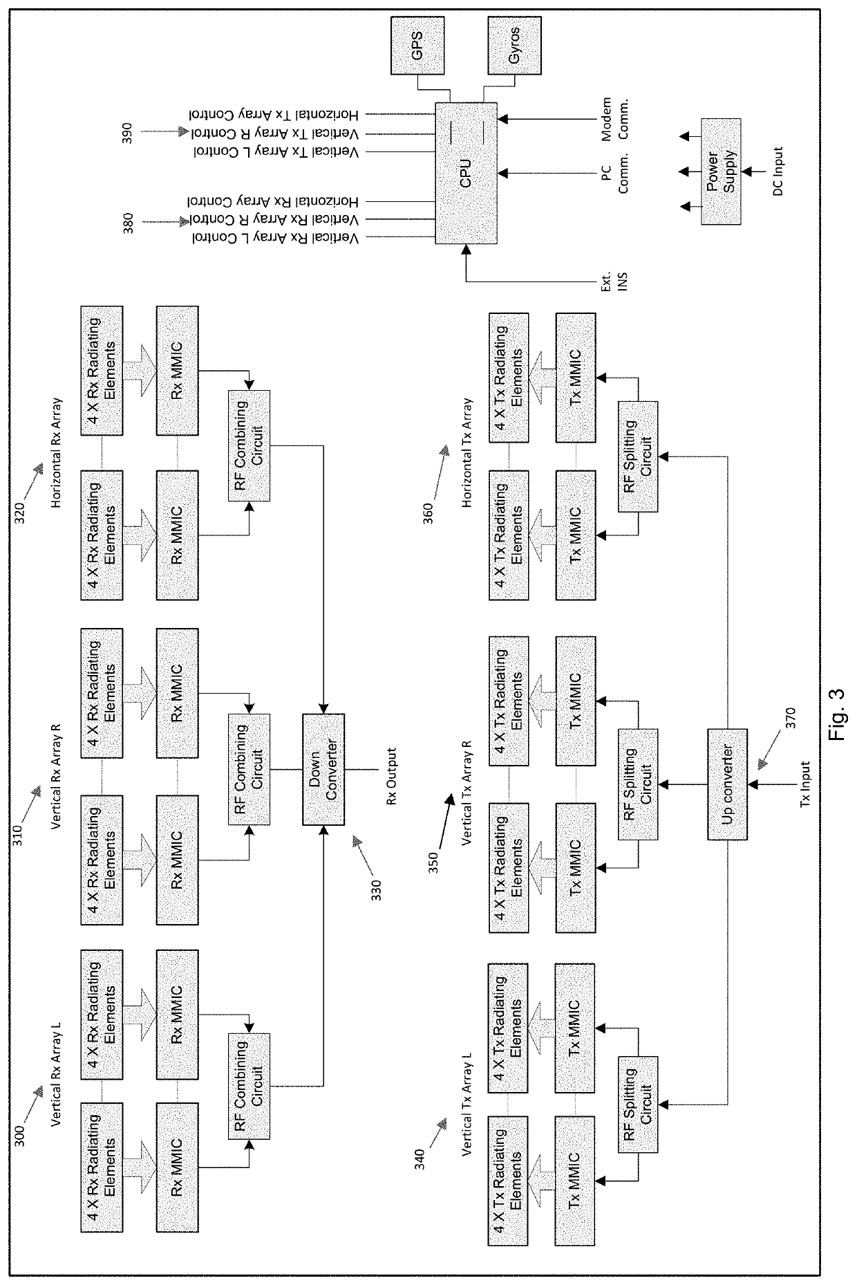
[0023]Wireless communications utilize antennas to transmit and receive signals between different devices. For example, a satellite communication system for commercial and / or non-commercial applications (e.g., aviation) may comprise antennas mounted on a remote station such as a fixed or mobile device (e.g., an aircraft), a satellite, and / or a ground earth station (GES) (e.g., a Hub station). The antennas may provide for reception and transmission of the electromagnetic signals communicated between, for example, the remote station(s) and / or other remote station(s) and / or Hub station(s). A variety of remote antenna types may be used including, but not limited to: steered flat panel antennas (e.g., mechanically steerable passive arrays and / or electronically steerable active arrays), reflectors and / or reflector arrays, hybrid steering antennas (combining mechanical steering with electronic steering), and electronic steerable antennas such as phased array antennas (PAA) which may include...


PUM


Abstract

Examples disclosed herein describe an antenna architecture (e.g., a planar electronically steered antenna architecture) that enables operation at low elevation angles, down to zero degrees from the satellite. The proposed ‘3SA’ architecture may improve power consumption and array footprints. The proposed ‘3SA’ architecture can support aero terminal implementation on aircraft, enabling the use of GEO, MEO and LEO satellites even in regions having low elevation angles. The architecture may include a horizontal antenna array and vertical antenna array as well as a controller for switching between the antenna arrays.

Description

CROSS-REFERENCE TO RELATED APPLICATIONS[0001]This application is a non-provisional of and claims priority to U.S. Provisional Patent Application No. 63 / 078,696, filed Sep. 15, 2020, which is hereby incorporated by reference in its entirety.TECHNICAL FIELD[0002]Aspects of the disclosure pertain to antennas for wireless communications. Some aspects pertain to electronically steerable array (ESA) antennas for wireless communications.BACKGROUND[0003]Wireless communication systems, including systems for communication via satellites, are being used for a variety of civil and military applications, including aviation, maritime, and land-mobility. Antennas may be used for transmitting and receiving wireless signals between various remote devices. In some cases, the antennas being used may exhibit high power consumption and high beam scan loss especially at low elevation angles towards the satellite. A higher beam scan loss results in lower reception and transmission gain values, which may l...

Claims


Application Information

Patent Timeline
Patent Type & Authority Applications(United States)
IPC IPC(8): H01Q1/28H01Q21/06H01Q1/42
CPCH01Q1/28H01Q1/42H01Q21/06H01Q1/286H01Q3/24H01Q21/28H01Q25/002
Inventor STOLERU, RONEN
Owner GILAT SATELLITE NETWORKS
Why Eureka
Try Eureka