Temperature Protective Device for Filter Capacitor Bank

Pending Publication Date: 2022-03-17
SANTAK ELECTRONICS SHENZHEN
View PDF0 Cites 0 Cited by
  • Summary
  • Abstract
  • Description
  • Claims
  • Application Information

AI Technical Summary

Benefits of technology

[0033]The temperature protective device of the present invention is concise in design. The single temperature sensor is used for monitoring a temperature abnormity of a bank of capacitors, and the temperature control circuit is used for executing corresponding instructions to protect th

Problems solved by technology

The capacitor bank will generate heat while filtering the high-frequency ripple current, and some capacitors in the capacitor bank may be prone to faults.
As a result, the whole capacitor bank or other parts of the circuit may be damaged.
However,

Method used


Image

  • Temperature Protective Device for Filter Capacitor Bank
  • Temperature Protective Device for Filter Capacitor Bank
  • Temperature Protective Device for Filter Capacitor Bank

Examples


Embodiment Construction

[0046]For the purpose of making purposes, technical solutions and advantages of the present invention clearer and more understandable, the present invention will be further described based on specific embodiments in conjunction with the accompanying drawings.

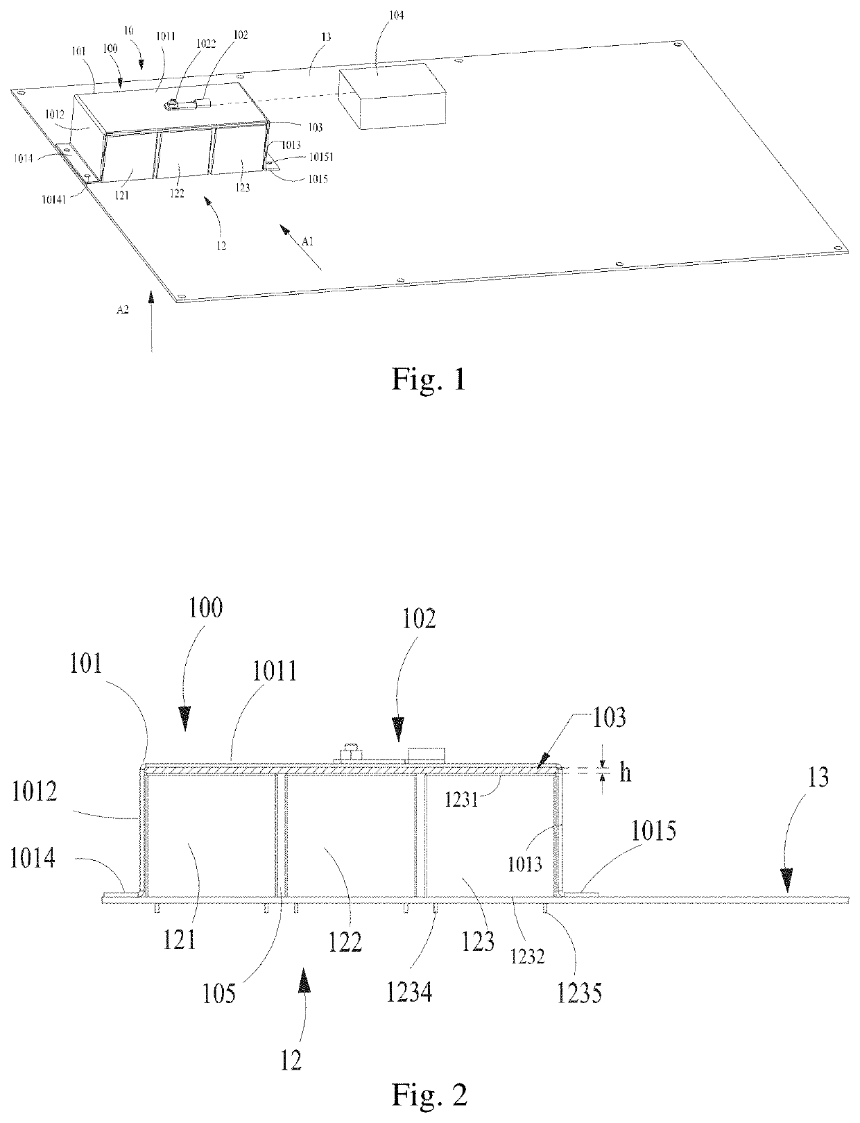
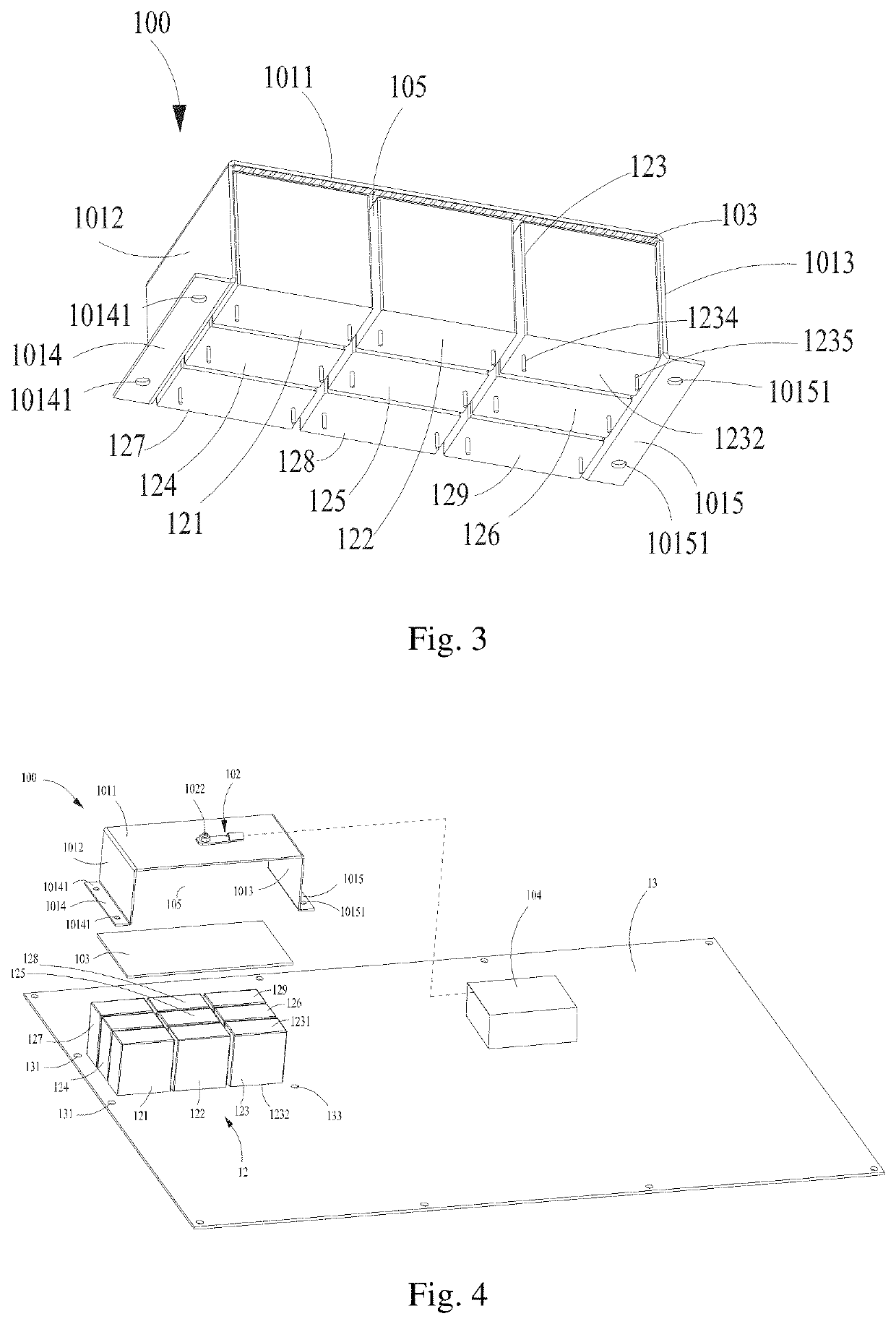
[0047]FIG. 1 is a 3D schematic diagram showing that a temperature protective device 10 and a capacitor bank 12 are fixed on a circuit board 13, according to a first embodiment of the present invention. As shown in FIG. 1, the circuit board 13 is preferably made of a printed circuit board. To avoid vagueness of the present invention, FIG. 1 does not show printed wires and a bonding pad on the circuit board 13. The capacitor bank 12 comprises nine capacitors electrically connected (eg. welding) to the circuit board 13 (introduction will be made in conjunction with FIG. 3-FIG. 4), wherein FIG. 1 only shows three capacitors 121, 122 and 123 thereof.

[0048]The temperature protective device 10 comprises a temperature measurement device...


PUM


Abstract

The present invention provides a temperature protective device for a filter capacitor bank. The capacitor bank comprises two or more capacitors which are arranged in an array manner. The temperature protective device comprises a temperature measurement device which comprises: a cover body covering the capacitor bank; a single temperature sensor fixed at a center area of the cover body, which is used for measuring a temperature value of the capacitor bank; and a heat conduction pad located between the cover body and the capacitor bank, wherein the heat conduction pad and the cover body have fitted shapes. The temperature protective device of the present invention saves cost and can accurately realize temperature protection of the capacitor bank.

Description

TECHNICAL FIELD[0001]The present invention relates to a temperature protective device, and more particularly relates to a temperature protective device for a filter capacitor bank.BACKGROUND ART[0002]In the prior art, a circuit may have a capacitor bank formed by parallel connection of a plurality of capacitors, which is used for, for example, filtering possible high-frequency ripple current in the circuit. The capacitor bank will generate heat while filtering the high-frequency ripple current, and some capacitors in the capacitor bank may be prone to faults. As a result, the whole capacitor bank or other parts of the circuit may be damaged. Therefore, it is necessary to detect the temperature of the capacitor bank in real time.[0003]On the other hand, the existing temperature protective device comprises a plurality of temperature measurement devices, wherein each temperature measurement device is used for measuring the temperature of a corresponding capacitor for conducting tempera...

Claims


Application Information

Patent Timeline
IPC IPC(8): H02J7/00H02J7/34G01R31/64
CPCH02J7/00309G01R31/64H02J7/345G05D23/24H01G2/14H01G4/40
Inventor LIU, DANZHENG, DAWEIOUYANG, SUIOU, LINGFUKANG, DEWU
Owner SANTAK ELECTRONICS SHENZHEN
Why Eureka
Try Eureka