
Storage device

a storage device and reagent technology, applied in the field of storage devices, can solve the problems of contaminating parts of the cartridge, affecting the integration of reagents on the cartridge, and amplicons moving between the parts,

Pending Publication Date: 2022-03-31
DNAE DIAGNOSTICS LTD
View PDF2 Cites 0 Cited by
  • Summary
  • Abstract
  • Description
  • Claims
  • Application Information

AI Technical Summary

Benefits of technology

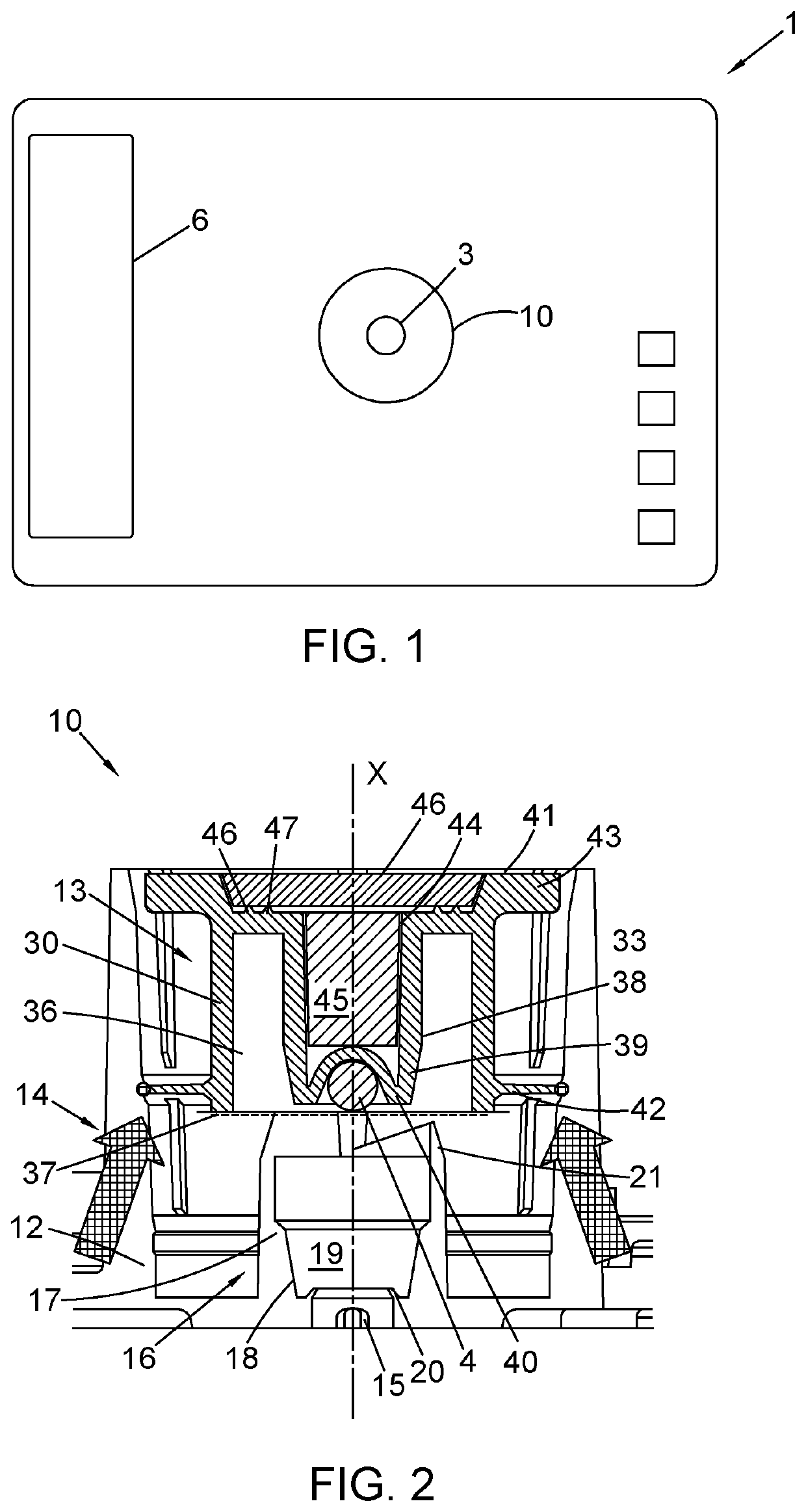
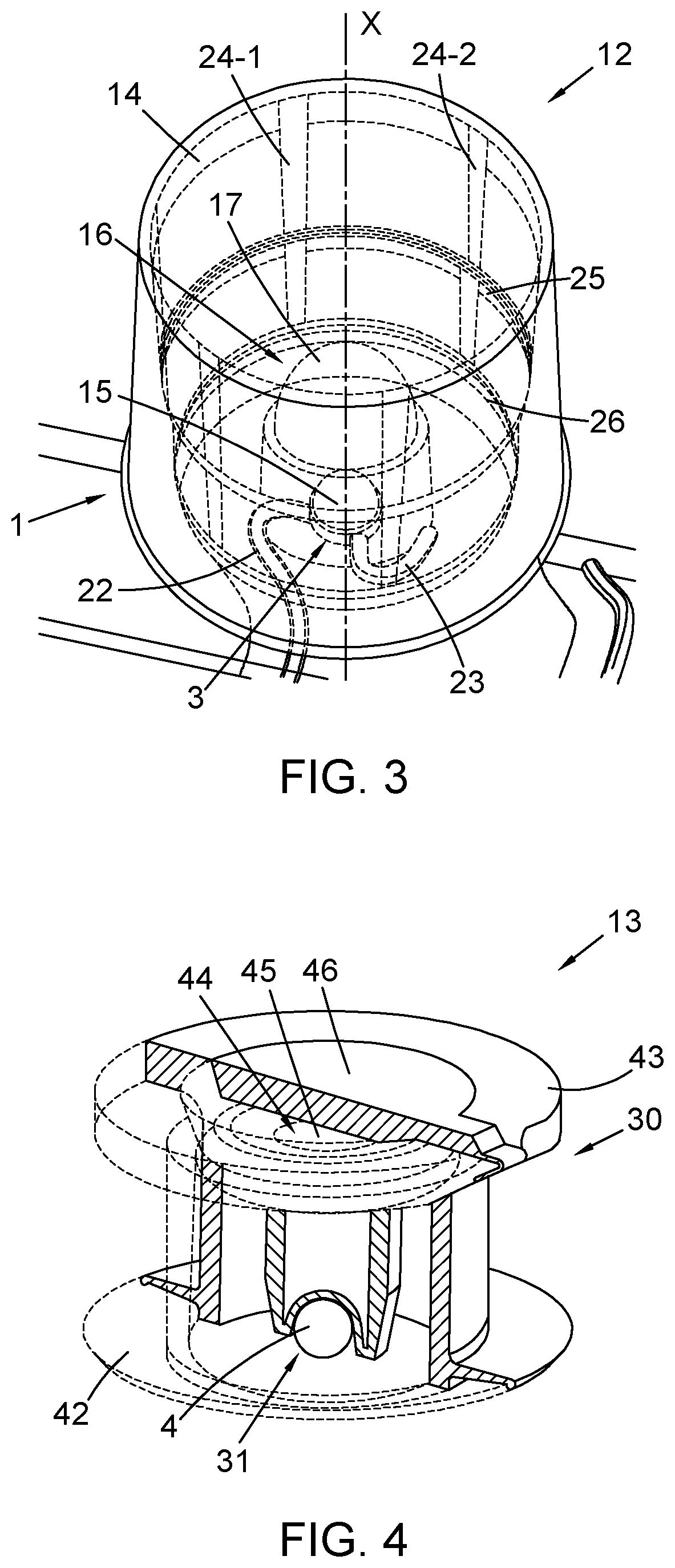
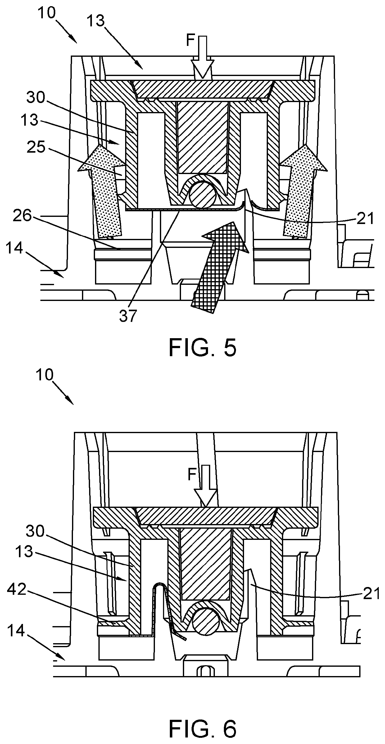
This patent describes a cartridge for a device used in molecular biology. The cartridge has a chimney, which is a cylindrical structure used to store and protect the desiccant used in the device. The chipmney can be made separate from or integrally formed with the cartridge, depending on manufacturing requirements and costs. The chipmney is cylindrical and has no corners, which reduces stress and manufacturing constraints. An O-ring is used to secure the bead holder to the chipmney, and the chipmney has vents to prevent pressure during manufacture and use. The housing of the device comprises a chimney and an intermediate wall, which helps to keep the reagent sealed when the device is actuated. The technical benefits of this design include improved protection and preservation of the desiccant, simplified manufacturing process, and improved performance of the molecular biology device.

Problems solved by technology

The integrity of reagents on a cartridge may be challenged by moisture ingress especially when it is stored for a protracted period of time.
Furthermore, if there is not efficient sealing between parts, amplicons can move between the parts and contaminate parts of the cartridge where they are not intended to be.

Method used


Image

  • Storage device
  • Storage device
  • Storage device

Examples


second embodiment

[0060]It will be understood that various changes and modifications may be made to storage device 10. A storage device 10 in accordance with the present invention is shown in FIG. 9. Like reference are used for like components.

[0061]The storage device 10 according to the second embodiment comprises alignment means 51 for aligning the bead holder 13 with the chimney 14. In particular, the alignment means 51 is operative to inhibit or limit rotation of the bead holder 13 relative to the chimney 14. The alignment means 51 comprises cooperating male and female features. In the present embodiment, the alignment means 51 comprises opposing first and second guide members 52A, 52B provided on the body 30. The first and second guide members 52A, 52B are arranged to travel in respective first and second channels 53A, 53B formed in the inner surface of the chimney 14. The first and second guide members 52A, 52B comprise respective first and second resilient arms 54A, 54B which are displaced inw...

third embodiment

[0064]The storage device 10 comprises an annular seal 60 between the bead holder 13 and the chimney 14. In the illustrated arrangement, the annular seal 60 comprises an O-ring, for example formed from an elastomeric material. One or both of the bead holder 13 and the chimney 14 may comprise an annular indentation 61, 62 for locating the O-ring. The annular indentation(s) 61 may be formed around the outer face of the bead holder 13. At least in certain embodiments, this arrangement may be alignment free and may be more tolerant of manufacturing variability. The chimney 14 in this embodiment may comprise an annular taper on the upper edge in order to facilitate assembly of the storage device 10. As shown in FIG. 11, the well 3 may optionally be formed in the base unit 12.

[0065]It will be appreciated that various changes and modifications can be made to the present invention without departing from the scope of the present application. For example, in a modified arrangement, the bead h...


PUM


Abstract

A device is provided for preserving the integrity of one or more reagents on a substantially planar cartridge. The device includes a chimney extending substantially perpendicular to the plane of the cartridge, a bead holder encapsulated within the chimney; and a piercing mechanism located within the chimney and configured to enable a bead to access the bead holder, in use.

Description

TECHNICAL FIELD[0001]The present disclosure relates to a storage device. Aspects of the invention relate to a device for preserving the integrity of one or more reagents; and to a cartridge comprising a device for preserving the integrity of one or more reagents.BACKGROUND[0002]It is known to store a dry reagent and a wet reagent on a diagnostic cartridge. The dry reagent may, for example, comprise a lyophilised bead. The dry reagent may be exposed to moisture in the form of a vapour from the wet reagent, for example. The integrity of reagents may be adversely affected by moisture ingress, especially during storage over a prolonged period of time. It has been recognised that it would be desirable to reduce the moisture vapour transfer rate from the wet reagent to the dry reagent. Furthermore, if there is not efficient sealing between parts, amplicons can move between different regions of the cartridge resulting in contamination.[0003]It is an aim of the present invention to address ...

Claims


Application Information

Patent Timeline
IPC IPC(8): B01L3/00
CPCB01L3/523B01L2200/16B01L2300/042B01L2300/0672B01L2300/0832B01L2300/044B01L2400/0683B01L2200/10B01L2300/0816B01L2400/0481B01L3/502715B01L2400/0478B01L3/50B01L3/502B01L3/508B01L3/52
Inventor SPRINGER, MATTHEWTASSONE, JOHN LUISCASTLE, SIMEON DOMINICPEARSON, LEE
Owner DNAE DIAGNOSTICS LTD
Learn More