
Method for strengthening and lifting high-rise building having raft foundation

a technology for building foundations and high-rise buildings, applied in foundation engineering, soil preservation, construction, etc., can solve problems such as uneven settlement, building sinkage, and threat to the structural safety of buildings, and achieve the effects of low damage to buildings, good overall stability, and controllable lifting speed and heigh

Pending Publication Date: 2022-03-31
BEIJING HENGXIANG HONGYE FOUND REINFORCEMENT TECH CO LTD
View PDF5 Cites 4 Cited by
  • Summary
  • Abstract
  • Description
  • Claims
  • Application Information

AI Technical Summary

Benefits of technology

The patent text describes a method for strengthening and lifting high-rise buildings with a raft foundation. The method solves problems associated with strengthening and lifting settlement of buildings with raft foundations. The method has the advantages of overall stability, controllable lifting speed and height, minimal damage to the building, and prevents re-settlement.

Problems solved by technology

Due to architectural reconnaissance, design, construction, or bad weather, etc., a built building will sink due to insufficient foundation strength.
Even cracks and damages will occur, posing a threat to the structural safety of the building.
When the construction of the building is completed, uneven settlement occurs.
However, the height of the residential building is ultrahigh, the load bearing on the top of the raft foundation is very large, and in addition, the pozzolanic stratum is not compact so that the technical problems of lifting correcting and foundation reinforcement of the building still cannot be solved by using the techniques in the above-mentioned patent application document.

Method used


Image

  • Method for strengthening and lifting high-rise building having raft foundation
  • Method for strengthening and lifting high-rise building having raft foundation
  • Method for strengthening and lifting high-rise building having raft foundation

Examples


embodiment 2

[0090]When the foundation of the building is a special stratum such as collapsible loess and miscellaneous fill, the hole drilling and grouting operation adopts the integrally advancing grouting process, but not the integrally retreating grouting. Because the drill rod needs to be drilled to the design depth at one time in the integrally retreating grouting construction, in the procedure of drilling into the design depth, the water ejected from the drill bit part will soften the surrounding soil body, resulting in the secondary settlement of the building. When the collapsible loess is drilled, although the drilling speed is high and there is not much water flowing out at the drill bit, the collapsible loess will sink once in the water. So it is impossible to use the scheme of one-time drilling into the design depth. When drilling into the miscellaneous fill soil layer, it often encounters backfilled schist and so on. When drilling into the schist, the drilling speed slows down and ...

embodiment 3

[0103]In embodiment 1, the lifting hole 4 is provided on the outer side of the raft foundation 1, avoiding the hole drilling of the raft foundation 1, protecting the raft foundation 1 from damage, and drilling without the need to adopt special tools such as water drill, thereby improving the working efficiency. However, sometimes there is insufficient operating space at the periphery of the building, and in this case, as shown in FIG. 20, lifting hole 4 needs to be provided inside the building. On the side to be lifted of the building, the vertical lifting hole 4 is arranged tightly contacting with the load bearing wall 2, the vertical lifting hole 4 penetrates the raft foundation 1, and the bottom of the hole extends to a position close to the bottom of the reinforcement 3.

[0104]A rebar protective layer on the surface of the raft foundation 1 is broken at the lifting hole 4 to expose the raft rebar. A water drill is used to drill downward between the rebar gaps of the raft foundati...

embodiment 4

[0108]With reference to FIG. 21, in practical buildings, it is sometimes encountered that two unit buildings are close to each other, and only about 10 cm of settlement joint is left in front of adjacent units. At this time, it is obviously inappropriate to arrange a lifting hole 4 on the immediately adjacent side of the building. Furthermore, since one lifting hole 4 is insufficient to uniformly lift the building upwards, so two lifting holes 4 are arranged at this moment. One lifting hole 4 provided as above by being provided inclinedly on the outer side of the building. The other lifting hole 4 is provided vertically at the inner side of the building close to the wall body of the building. The two lifting holes 4 are respectively provided on different sides of a corner of the building. When lifting is performed, grouting lifting is performed at the same time.

[0109]In the reinforcement grouting and lifting grouting mentioned in the above embodiments, as well as the filling groutin...


PUM


Abstract

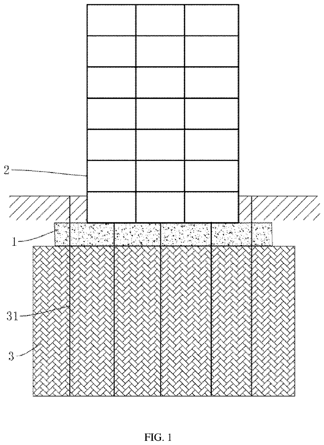
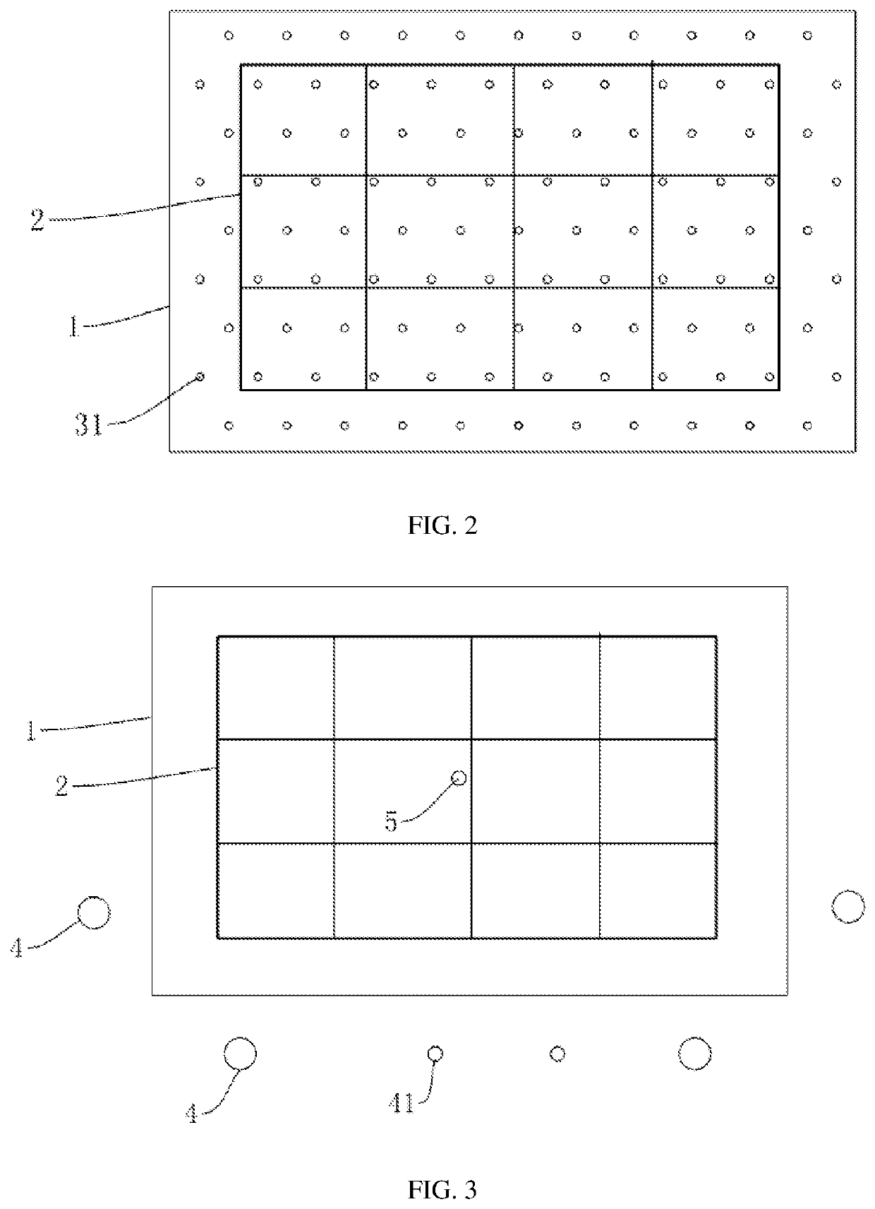
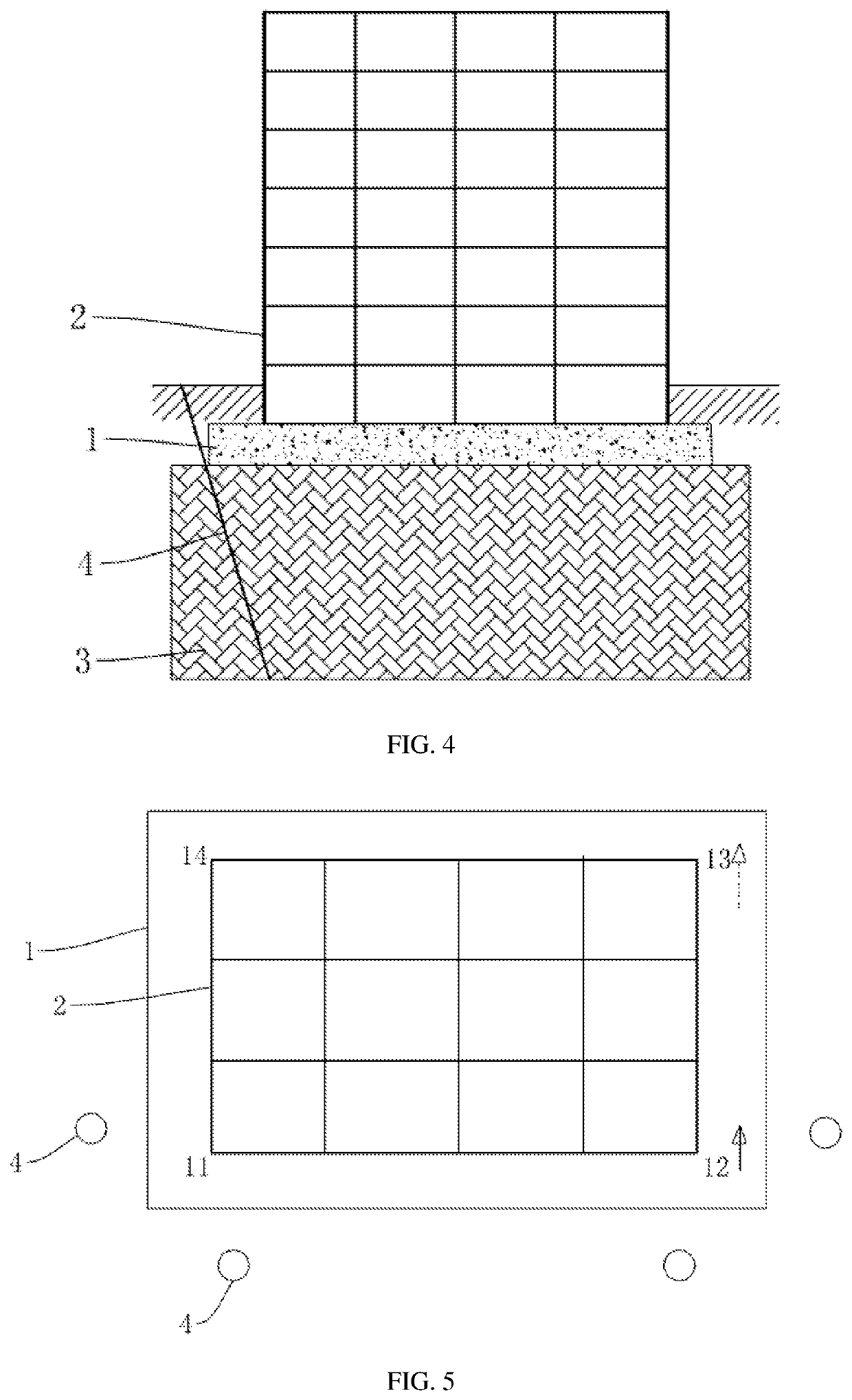
Disclosed is a method for strengthening and lifting a high-rise building that has a raft foundation, comprising: arranging a plurality of measuring points at intervals around the outer contour of a building, and determining the side to be lifted of the building according to the elevation of the measuring points; distributing a plurality of reinforcement grouting holes perpendicular to a raft foundation at intervals within the range of the raft foundation, and using pressure grouting in the reinforcement grouting holes to form a reinforcement under the raft foundation; laying downwardly inclined lifting holes on the outer side of the raft foundation at two ends close to the side to be lifted of the building; and performing simultaneous pressure grouting in the lifting holes to lift the side to be lifted of the building.

Description

CROSS-REFERENCE TO RELATED APPLICATION[0001]The present application is a continuation of international application of PCT application No. PCT / CN2019 / 107379 filed on Sep. 23, 2019, which claims the priority benefit of China application No. 201910517280.6 filed on Jun. 14, 2019. The entirety of the above-mentioned patent applications is incorporated herein by reference and made a part of this specification.TECHNICAL FIELD[0002]The present application relates to the technical field of building foundation lifting and strengthening, and more particularly, to a method for strengthening and lifting a high-rise building having a raft foundation.BACKGROUND ART[0003]Due to architectural reconnaissance, design, construction, or bad weather, etc., a built building will sink due to insufficient foundation strength. If the inclination value of the building exceeds the allowable inclination value, the normal use will be affected. Even cracks and damages will occur, posing a threat to the structura...

Claims


Application Information

Patent Timeline
Patent Type & Authority Applications(United States)
IPC IPC(8): E02D35/00E02D37/00
CPCE02D35/005E02D2300/0018E02D2250/003E02D37/00E02D3/12E02D35/00
Inventor CUI, XUEDONGWU, JIGUANGCUI, TENGYUE
Owner BEIJING HENGXIANG HONGYE FOUND REINFORCEMENT TECH CO LTD
Learn More