High throughput tribometer

a tribometer and high throughput technology, applied in the field of high throughput tribometers, can solve the problems that increasing the testing speed is not a viable strategy to increase throughput or enhance resolution

Pending Publication Date: 2022-04-07
NAT TECH & ENG SOLUTIONS OF SANDIA LLC
View PDF0 Cites 0 Cited by
  • Summary
  • Abstract
  • Description
  • Claims
  • Application Information

AI Technical Summary

Benefits of technology

[0005]1. The present invention is directed to a system to rapidly and automatically exchange the counterface of a high throughput tribometer. The system comprises a carousel comprising a plurality of exchange tools; a selector motor for rotating

Problems solved by technology

Standardized methods typically require a particular testing speed to obtain performance results, such th

Method used


Image

  • High throughput tribometer
  • High throughput tribometer
  • High throughput tribometer

Examples


Embodiment Construction

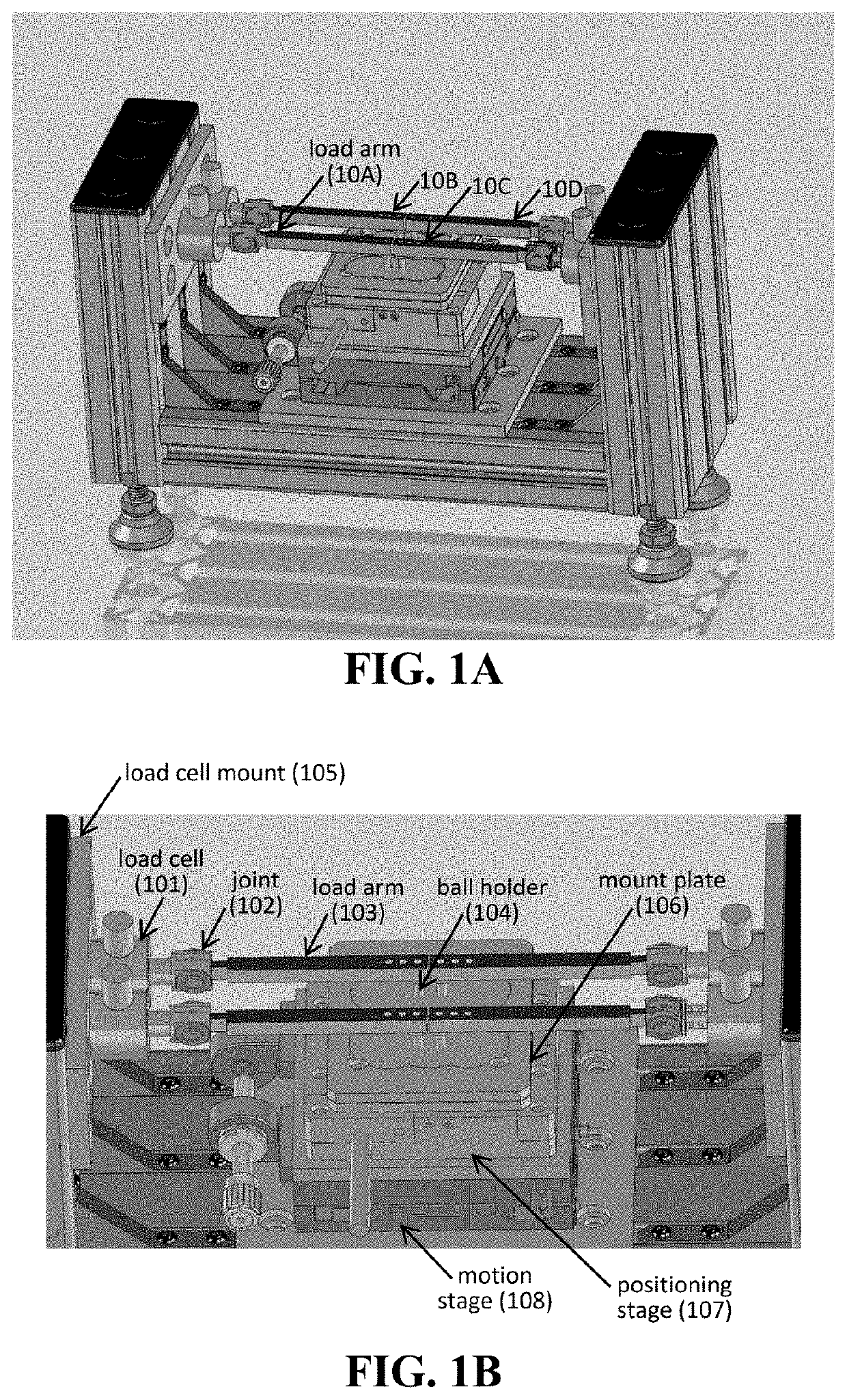
[0021]The present invention relates, in part, to systems for characterizing force (e.g., friction and wear). In one embodiment, a tribometer allows for wear testing of samples in a high throughput manner.

[0022]Systems for Wear Testing

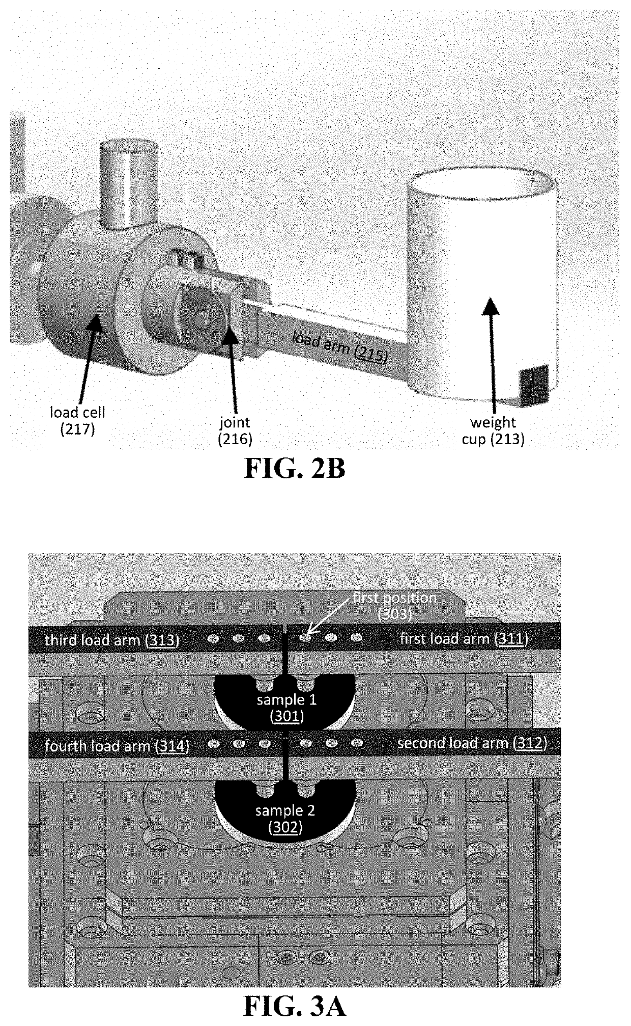
[0023]As described in U.S. application Ser. No. 16 / 513,197, a system for wear testing can comprise a plurality of testers, in which each tester can be independently controlled to apply a particular force to a sample(s). In one embodiment of the system, each tester can be in proximity to one sample, thereby allowing each tester to conduct wear tests on each sample in an independent manner. Alternatively, the system can comprise a plurality of testers is in proximity to one sample, thereby allowing each tester to conduct wear tests on different portions of the same sample.

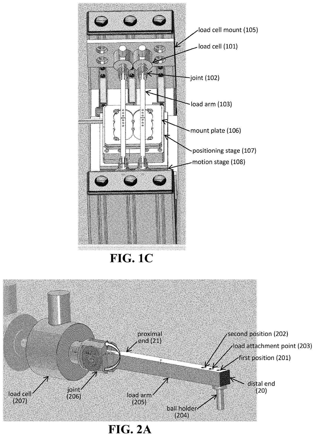
[0024]Each tester can include one or more components to apply a force to a sample surface. In one embodiment, a tester includes a load arm having a proximal end and a distal end. Whereas...


PUM


Abstract

The present invention relates, in part, to systems for characterizing force (e.g., friction, and wear). In one embodiment, a tribometer allows for wear testing of samples in a high throughput manner.

Description

CROSS-REFERENCE TO RELATED APPLICATIONS[0001]This application is a continuation-in-part of U.S. application Ser. No. 16 / 513,197, filed Jul. 16, 2019, which claims the benefit of U.S. Provisional Application No. 62 / 714,384, filed Aug. 3, 2018, both of which are hereby incorporated by reference in their entirety.STATEMENT OF GOVERNMENT INTEREST[0002]This invention was made with Government support under Contract No. DE-NA0003525 awarded by the United States Department of Energy / National Nuclear Security Administration. The Government has certain rights in the invention.FIELD OF THE INVENTION[0003]The present invention relates, in part, to systems for characterizing force (e.g., friction and wear). In one embodiment, a tribometer allows for wear testing of samples in a high throughput manner.BACKGROUND OF THE INVENTION[0004]Current state-of-the-art generally relies on single sample testing of material characteristics. Standardized methods typically require a particular testing speed to ...

Claims


Application Information

Patent Timeline
IPC IPC(8): G01N3/56G01N3/04G01N3/16
CPCG01N3/56G01N3/165G01N3/04G01N19/02G01N2203/0206
Inventor NATION, BRENDAN L.DUGGER, MICHAEL T.CURRY, JOHN
Owner NAT TECH & ENG SOLUTIONS OF SANDIA LLC
Why Eureka
Try Eureka