Rotary reciprocating frictional wear testing machine

A friction and wear test and test force technology, applied in the direction of testing wear resistance, etc., can solve the problems affecting the process of automatic collection, affecting the measurement accuracy, affecting the accuracy of materials, etc., to eliminate the dead weight of the structure, accurate measurement data, and save equipment. effect of funds

Pending Publication Date: 2019-12-03
济南益华摩擦学测试技术有限公司
View PDF0 Cites 18 Cited by
  • Summary
  • Abstract
  • Description
  • Claims
  • Application Information

AI Technical Summary

Problems solved by technology

[0004] In addition, the secondary problem to be solved by the present invention is: in various vertical loading force test equipment, the self-weight in the sensor measurement structure also needs to be measured, and the directions of self-gravity and loading force are opposite, and its measurement process in the prior art is very It is annoying to lock, so this part of the value is often removed by manual input, which affects the process of automatic collection and affects the measurement accuracy, so finding a new structure method can solve the above problems
[0005] Another secondary problem to be solved by the present invention is: in the friction and wear test of the reciprocating column tile, the contact between the upper and lower samples is a very important index, and the contact of the upper and lower sample friction surfaces is crucial to the frictio

Method used


Image

  • Rotary reciprocating frictional wear testing machine
  • Rotary reciprocating frictional wear testing machine
  • Rotary reciprocating frictional wear testing machine

Examples


Embodiment Construction

[0032] The present invention will be further described below in conjunction with accompanying drawing by non-limiting embodiment:

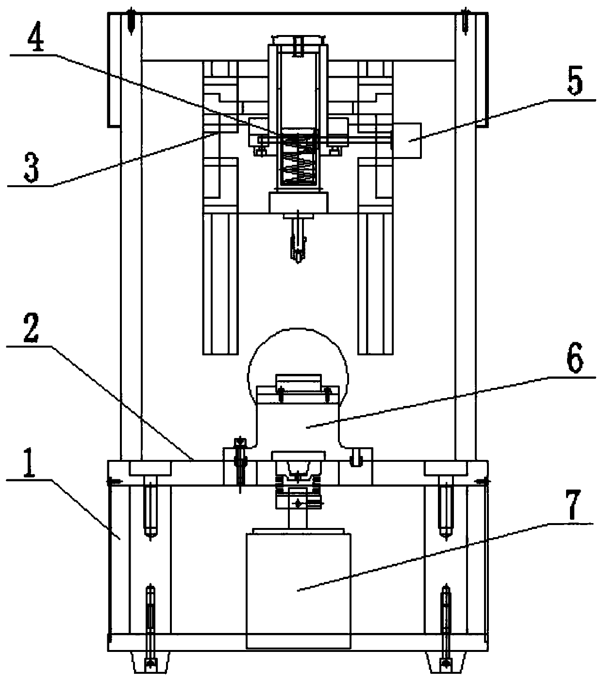
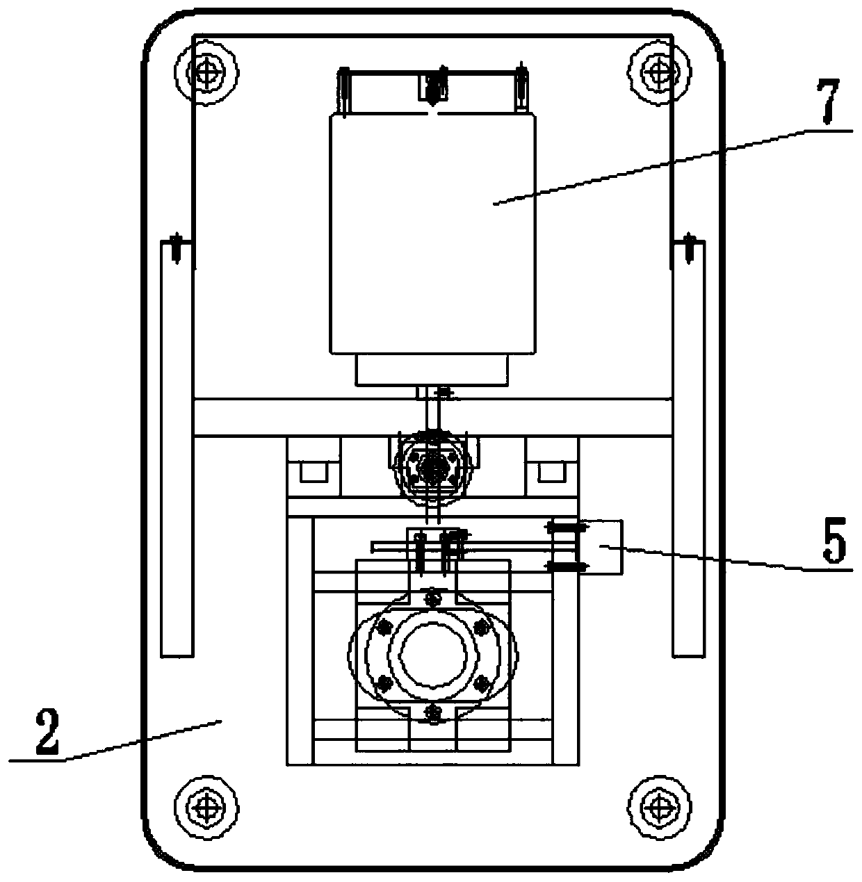
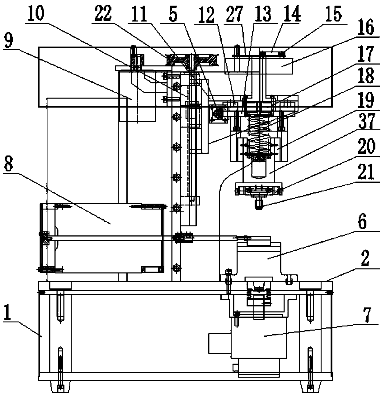
[0033] As shown in the drawings, a rotary reciprocating friction and wear testing machine includes a frame 1 provided with a frame workbench 2 , a rotary test device, a linear reciprocating test device, a test force loading mechanism, and a sample clamping module 6 . The rotation testing device includes a rotation driving motor 7 , and the rotation driving motor 7 is vertically arranged in the frame 1 and located at the lower part of the frame workbench 2 . The linear reciprocating test device includes a reciprocating linear motor 8, the reciprocating linear motor 8 is a voice coil motor, and the reciprocating linear motor 8 is horizontally arranged on the frame 1 and is located on the frame workbench 2 upper part. The axis of the reciprocating linear motor 8 and the axis of the rotary drive motor 7 are vertically intersected. The sample clampin...


PUM


Abstract

The invention discloses a rotary reciprocating frictional wear testing machine which comprises a rack provided with a rack workbench, a rotation test device, a linear reciprocating test device, a testforce loading mechanism and a sample clamping module. The rotation test device comprises a rotation driving motor. The rotary driving motor is vertically arranged in the rack and is positioned at a lower part of the rack workbench. The linear reciprocating test device comprises a reciprocating motion linear motor which is a voice coil motor. The reciprocating motion linear motor is horizontally arranged on the rack, an axis of the reciprocating motion linear motor perpendicularly intersects with an axis of the rotary driving motor, the sample clamping module is detachably mounted on the rackworkbench and is coaxial with the axis of the rotary driving motor. The test force loading mechanism comprises a lifting mechanism and a force application mechanism, the lifting mechanism is arrangedon the rack, the force application mechanism comprises a force application shaft, a measurement sensor connected to the force application shaft and an upper sample clamp connected to a lower end of the force application shaft, and the force application mechanism is connected to the lifting mechanism.

Description

technical field [0001] The invention relates to a rotary reciprocating friction and wear testing machine, which belongs to the technical field of friction and wear testing machines. Background technique [0002] The friction and wear testing machine in the prior art has the defect of single function, for example, the linear reciprocating friction and wear testing machine can only perform the test of reciprocating friction and wear, while the rotary friction and wear testing machine can only perform the test of rotating friction and wear. Due to the single function of the existing friction and wear testing machines, users often need to configure testing machines with different functions, resulting in a large waste of funds. Moreover, the linear reciprocating motor generally used in the linear reciprocating friction and wear testing machine in the prior art is often only applicable to the low frequency range or high frequency range, the applicable range is narrow, and it canno...

Claims


Application Information

Patent Timeline
IPC IPC(8): G01N3/56
CPCG01N3/56
Inventor 肖华程俊
Owner 济南益华摩擦学测试技术有限公司
Why Eureka
Try Eureka