
Method for Determining the Carbon Footprint of a Product in Production Processes of a Production Plant

Pending Publication Date: 2022-04-07
BASF SE
View PDF7 Cites 0 Cited by
  • Summary
  • Abstract
  • Description
  • Claims
  • Application Information

AI Technical Summary

Benefits of technology

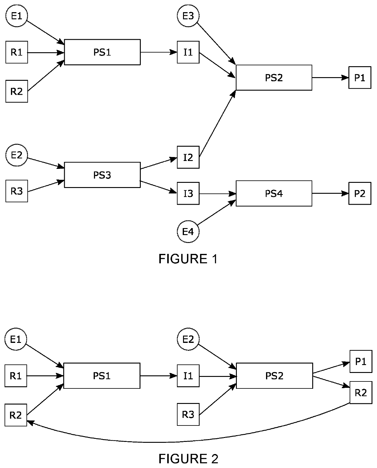
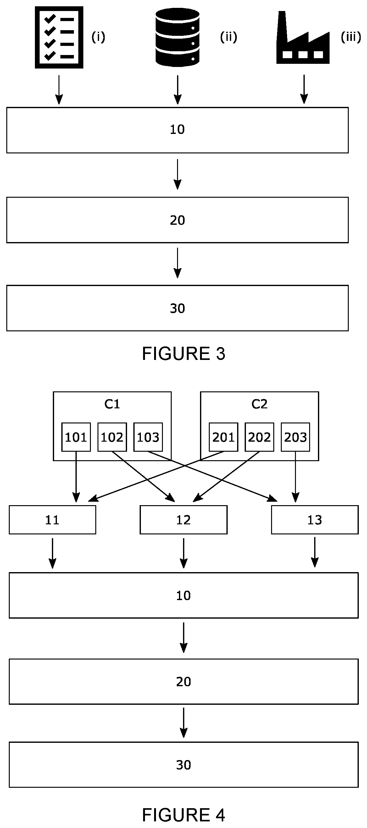
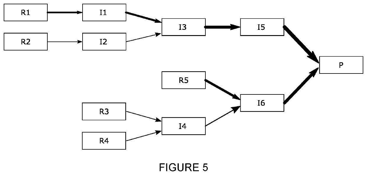
The patent describes a method for calculating the carbon footprint of a product based on the actual situation of production processes in a production plant. The method is fast and allows for frequent updates of carbon footprints based on process data. The goal is to help minimize the carbon footprint of products in a production plant. The method uses a computer-implemented method that involves gathering process data, the carbon footprint of raw materials, energy data, and determining the carbon footprint of the product by taking into account the process data, the carbon footprint of the raw materials, and energy data. The method can be used to calculate and optimize carbon footprints of products and their downstream products. The patent also describes a system for determining the carbon footprint of a product in a production plant.

Problems solved by technology

Specifically, this includes the greenhouse gas emissions of raw materials obtained from suppliers.
However, in a modern production plant representing a complex system of interconnected process steps, different production processes influence each other, for example because they both use steam generated by a power plant.
As an example, a reduced usage of the power plant may reduce its efficiency, so the same amount of steam produces more greenhouse gas emissions, for example because there is no use for the remaining steam, but the power plant output cannot be reduced because the electricity demand is unchanged.
This makes the determination of PCFs for the companies' products very expensive and time-consuming.
Moreover, existing standards for PCF determination leave room for choices and interpretation, and there is no unique and unambiguous method how to allocate the scope 1 and scope 2 emissions of production plants to individual products.
Traditionally PCFs are calculated only case-by-case by individual experts—hence, this bears a high risk of making inconsistent methodological choices.
Therefore, comparability of the resulting PCFs stemming from different sources and / or produced at different points in time is currently not given.

Method used


Image

  • Method for Determining the Carbon Footprint of a Product in Production Processes of a Production Plant
  • Method for Determining the Carbon Footprint of a Product in Production Processes of a Production Plant
  • Method for Determining the Carbon Footprint of a Product in Production Processes of a Production Plant

Examples


Embodiment Construction

[0021]In some embodiments, a method according to the present invention determines the carbon footprint of products. In the context of the present invention, “carbon footprint” relates to the amount of greenhouse gases emitted or removed in a production process of a production plant. The carbon footprint may relate to the total amount of greenhouse gases emitted or removed in the production process e.g. from extracting natural resources to the product as it leaves the production plant. In the context of the present invention, the carbon footprint may not include any greenhouse gas emission later on in the lifetime of a product. For example, for a car the carbon footprint in the context of the present invention is the amount of greenhouse gases emitted to produce the car, but not the emissions caused by using the car once it has left the production plant. The amount of the carbon footprint is typically expressed as carbon dioxide equivalents, so the amount of carbon dioxide with the s...


PUM


Abstract

The present invention is in the field of computer-implemented methods for determining the carbon footprint of a product in a production process in a production plant, in particular of a product in interconnected production processes. Certain embodiments of the present invention relate to a computer-implemented method for determining the carbon footprint of a product produced in production process of a production plant.

Description

CROSS-REFERENCE TO RELATED APPLICATION(S)[0001]This application claims the benefit of priority of European Patent Application No. 20200091.5, filed on Oct. 5, 2020, the disclosure of which is hereby incorporated by reference herein in its entirety.TECHNICAL FIELD[0002]The present invention is in the field of computer-implemented methods for determining the carbon footprint of a product in production processes in a production plant, in particular of a product in interconnected production processes.BACKGROUND[0003]The significance of climate protection measures is growing rapidly in the perception of the public, regulators and financial investors. Major companies have announced ambitious short-term CO2 reduction targets, including emissions related to purchased raw materials as, for example, required by the Science-Based Targets Initiative (SBTI). Therefore, transparency on Product Carbon Footprints (PCF) and options to reduce the PCF are increasingly demanded by customers.[0004]Accor...

Claims


Application Information

Patent Timeline
IPC IPC(8): G06Q30/00
CPCG06Q30/018G06Q50/04G06Q10/06393Y02P90/30Y02P90/845G05B19/4183G05B19/41865G05B19/4188G05B19/406G05B23/0294G05B2219/32351G05B2219/32354G05B2219/34351
Inventor SCHOENEBOOM, JANHUBER, OLAF
Owner BASF SE
Learn More