Steering wheel indicating paddle for displaying power rotating speed of automobile

a technology of rotating speed and steering wheel, which is applied in the direction of electrical equipment, vehicle components, transportation and packaging, etc., can solve the problems of visual bringing of aesthetic fatigue, poor experience effect of products, and inability to be linked relatively with gear shifting, so as to improve the safety of vehicles

Active Publication Date: 2022-04-21
SHENZHEN LUOHE IMPORT & EXPORT CO LTD
View PDF4 Cites 0 Cited by
  • Summary
  • Abstract
  • Description
  • Claims
  • Application Information

AI Technical Summary

Benefits of technology

[0004]Aiming at deficiencies in the prior art, the objective of the present invention is to provide a steering wheel indicating paddle for displaying data conditions such as a power rotating speed of an automobile, a pressure of an air inlet manifold and a load of an engine. In use, a gear shifting indicating lamp can help a driver judge a gear shifting time better without reviewing a revolution meter, which further improves the safety of the vehicle. The driver can put a line of sight on a road all the time.
[0017]With adoption of the above-mentioned scheme, according to the present invention, the OBD signal access circuit is connected with the OBD port of the automobile, so that it acquires a rotating speed condition of an engine. An effect of displaying a power rotating speed of the automobile on the paddle can be realized by means of wireless or wired communication and control of the lamp panel of a marquee on the paddle to work correspondingly, thereby giving a user more intuitive observation. The integral dynamic sense of beauty is also enhanced, thereby giving the user better product experience.

Problems solved by technology

However, at the present, existing DIY refit shift paddles usually have art layout in appearance, are prone to bringing aesthetic fatigue visually, and cannot be linked relatively with gear shifting work of the automobile.
Therefore, as far as the user is concerned, the product is poor in experience effect.

Method used


Image

  • Steering wheel indicating paddle for displaying power rotating speed of automobile
  • Steering wheel indicating paddle for displaying power rotating speed of automobile
  • Steering wheel indicating paddle for displaying power rotating speed of automobile

Examples


Embodiment Construction

[0026]Detailed description is made on the embodiments of the present invention below in combination with drawings. However, the present invention can be implemented by various different modes defined and covered by Claims.

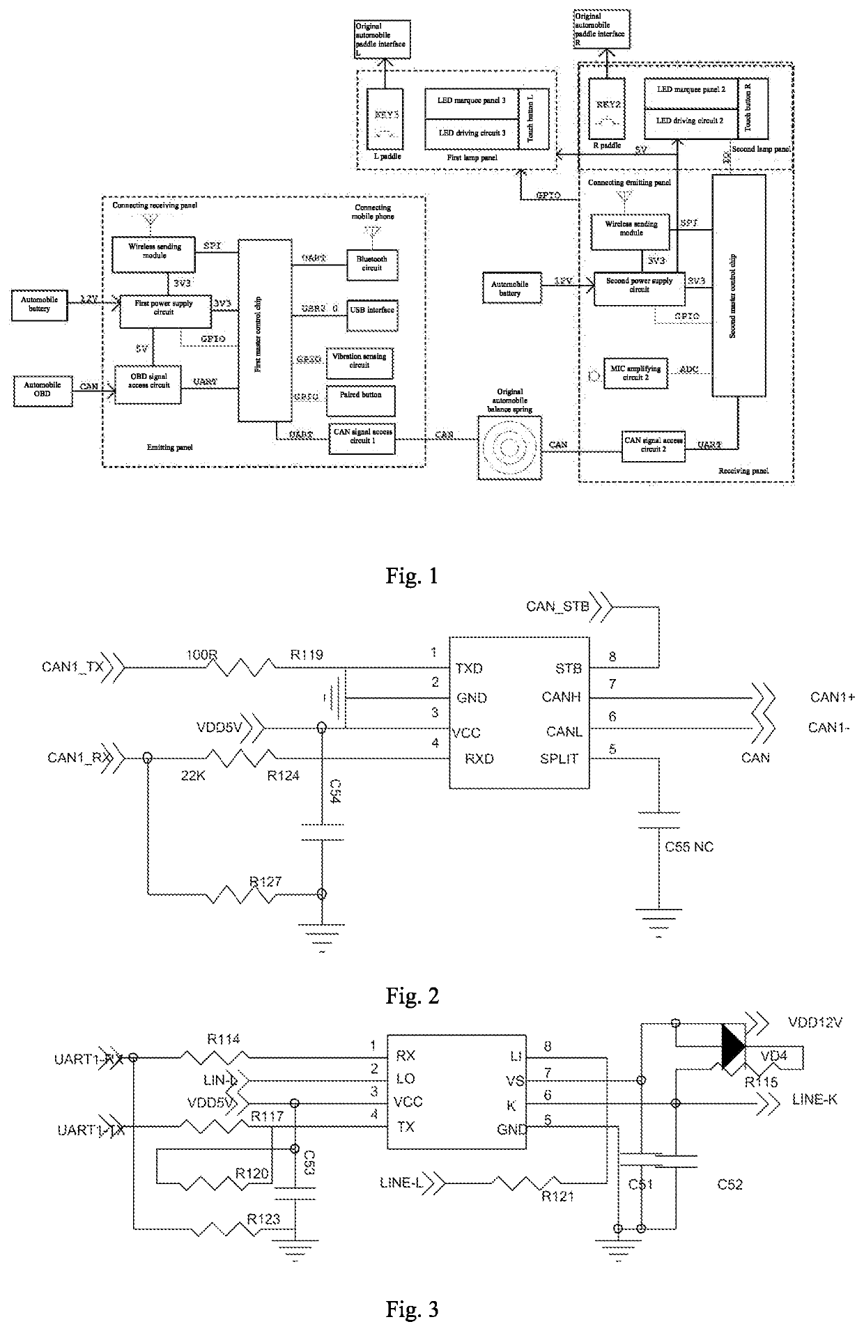
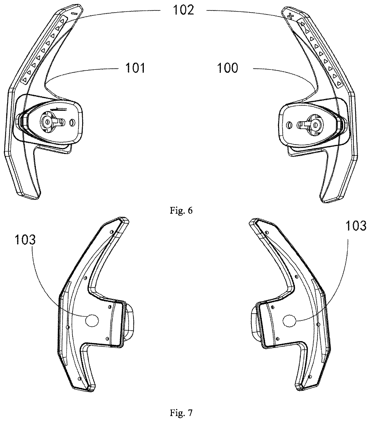
[0027]As shown in FIG. 1 to FIG. 7, a steering wheel indicating paddle for displaying a power rotating speed of an automobile includes an emitting panel connected with an OBD port of the automobile, a receiving panel mounted on an R paddle 100 or an L paddle 101 of the automobile, a first lamp panel mounted on another paddle and a second lamp panel integrated to the receiving panel;

[0028]wherein the emitting panel includes an OBD signal access circuit, a first master control chip, a first power supply circuit and a wireless sending module, the receiving panel includes a second master control chip, a second power supply circuit and a wireless sending module, and the first lamp panel and the second lamp panel both are provided with lamp panels of marquees and LED dri...


PUM


Abstract

The present invention discloses a steering wheel indicating paddle for displaying a power rotating speed of an automobile. The paddle comprises an emitting panel connected with an OBD port of the automobile, a receiving panel mounted on an R paddle or an L paddle of the automobile, a first lamp panel mounted on another paddle and a second lamp panel integrated to the receiving panel. The emitting panel comprises an OBD signal access circuit, a first master control chip, a first power supply circuit and a wireless sending module. The receiving panel comprises a second master control chip, a second power supply circuit and a wireless sending module. According to the present invention, the OBD signal access circuit is connected with the OBD port of the automobile, so that it acquires a rotating speed condition of an engine.

Description

BACKGROUND OF THE INVENTION1. Technical Field[0001]The present invention relates to the technical field of automobile accessories, in particular to a steering wheel indicating paddle for displaying a power rotating speed of an automobile.2. Description of Related Art[0002]With the continuous development of science and technology, gear shift of an automobile is not just limited to gear shift by stepping on a clutch. In some vehicles, shift paddles are arranged on steeling wheels to play a role of completing upshifting and downshifting operations without putting both hands of a driver aside the steering wheels. The driver usually needs to push the gear position of the shift paddle to D, S or manual modes. By using the shift paddle, the driver can complete upshifting and downshifting operations without putting both hands aside the steering wheel. Relatively common shift paddle positions are left and right sides of an arc in the steering wheel. When the vehicle is switched from D shift ...

Claims


Application Information

Patent Timeline
Patent Type & Authority Applications(United States)
IPC IPC(8): B60K35/00H05B47/19H05B47/18H05B45/30
CPCB60K35/00H05B47/19B60K2370/782H05B45/30H05B47/18B60K2370/152B60K2370/338
Inventor ZHANG, QINGYUN
Owner SHENZHEN LUOHE IMPORT & EXPORT CO LTD
Why Eureka
Try Eureka