Rear-view mirror with display function

a rear-view mirror and display function technology, applied in the field of rear-view mirrors, can solve the problems of fatigue and dazzling, people's limited field of vision, and drivers still cannot see the surrounding vehicles, so as to improve the driving safety of drivers

Pending Publication Date: 2022-04-28
UNIMICRON TECH CORP
View PDF5 Cites 0 Cited by
  • Summary
  • Abstract
  • Description
  • Claims
  • Application Information

AI Technical Summary

Benefits of technology

[0005]The disclosure is directed to a rear-view mirror with a

Problems solved by technology

Generally, people have a limited field of vision when driving a vehicle.
Even if a blind spot warning system is installed, such a device only flashes light at edges of the left side and the right side rear-view mirrors or sends audible warnings, and the driver still cannot actually see the surrounding vehicles.
In addition, the existing digital LCD display installed on the interior rear-view mirror is subject to a backlight brightness adjustment design (a turn-on/off function), and thus the displayed images are easily

Method used


Image

  • Rear-view mirror with display function
  • Rear-view mirror with display function
  • Rear-view mirror with display function

Examples


Embodiment Construction

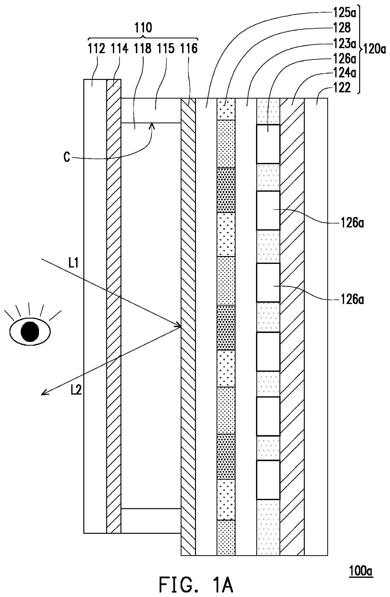
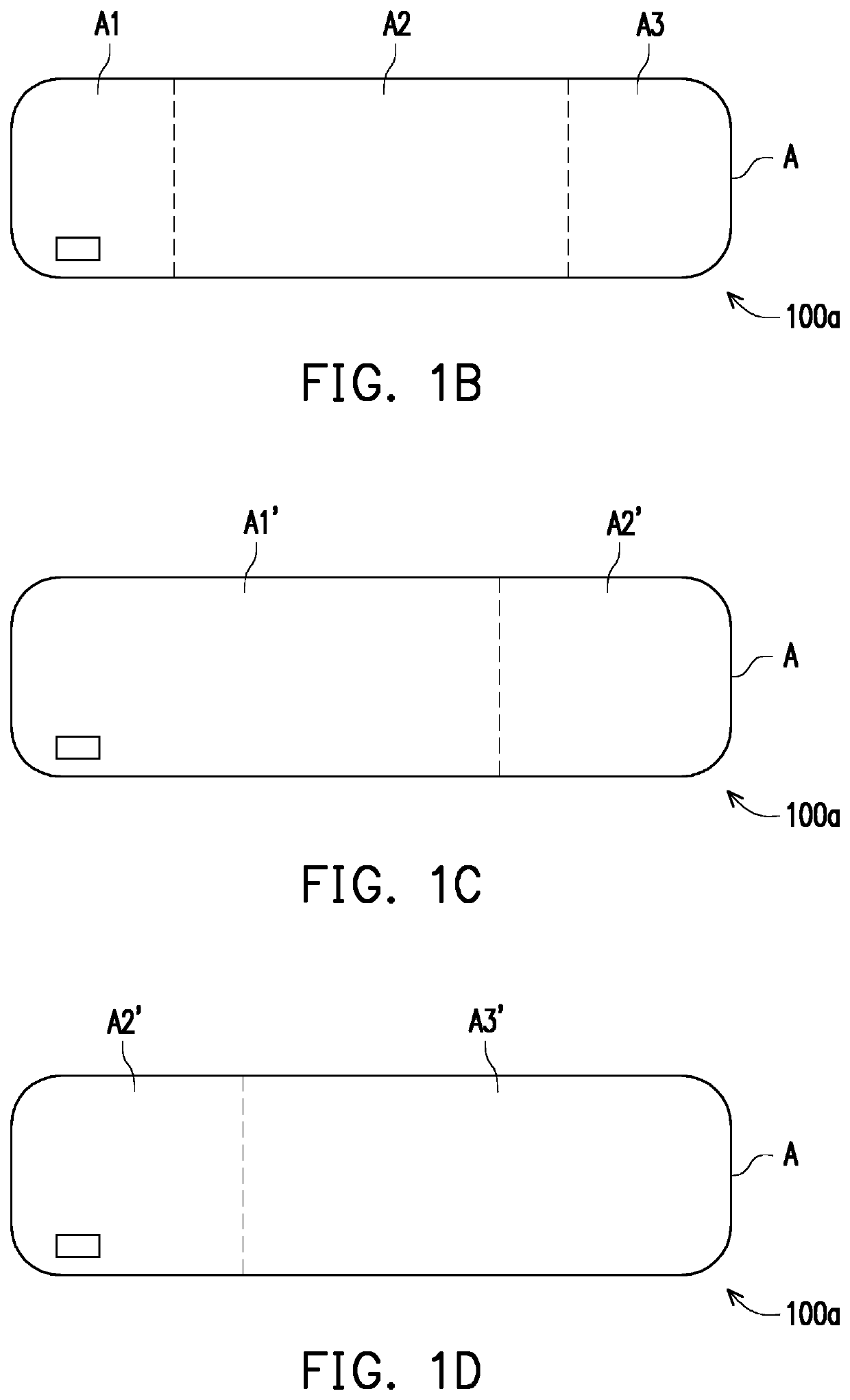
[0036]FIG. 1A is a schematic diagram of a rear-view mirror with a display function according to an embodiment of the disclosure. FIG. 1B to 1D are schematic diagrams of image frames of the rear-view mirror depicted in FIG. 1A in different states. As shown in FIG. 1A, in the embodiment, the rear-view mirror 100a with a display function includes a rear-view mirror body 110 and a display structure layer 120a. The display structure layer 120a is disposed on one side of the rear-view mirror body 110 and includes a plurality of light-emitting diodes 126a and a driving circuit layer 124a. The light-emitting diodes 126a are located between the rear-view mirror body 110 and the driving circuit layer 124a, and the light-emitting diodes 126a are electrically connected to the driving circuit layer 124a. The rear-view mirror 100a is, for example, a vehicle interior rear-view mirror.

[0037]In detail, in the embodiment, the rear-view mirror body 110 includes a substrate 112, a transparent electrode...


PUM


Abstract

A rear-view mirror with a display function includes a rear-view mirror body and a display structure layer. The display structure layer is disposed on one side of the rear-view mirror body and includes a plurality of light-emitting diodes and a driving circuit layer. The light-emitting diodes are located between the rear-view mirror body and the driving circuit layer. The light-emitting diodes are electrically connected to the driving circuit layer.

Description

CROSS-REFERENCE TO RELATED APPLICATION[0001]This application claims the priority benefit of Taiwan application serial no. 109136850, filed on Oct. 23, 2020. The entirety of the above-mentioned patent application is hereby incorporated by reference herein and made a part of this specification.BACKGROUNDTechnical Field[0002]The disclosure relates to a rear-view mirror, and particularly relates to a rear-view mirror with a display function.Description of Related Art[0003]Generally, people have a limited field of vision when driving a vehicle. Vehicle drivers may only determine surrounding and rear vehicles when driving on the road through a left side and a right side rear-view mirrors and an interior rear-view mirror. Therefore, the driver's line of sight has blind spots, i.e., the so-called “blind zones”. If motorcycles or vehicles enter the rear blind zones on both sides, the driver cannot detect the presence of other vehicles through the left side and the right side rear-view mirror...

Claims


Application Information

Patent Timeline
IPC IPC(8): B60R1/12B60R1/08
CPCB60R1/1207B60R2001/1215B60R1/08G02F1/157G02F1/155B60R1/12B60R1/088G02F1/133603G02F1/133614
Inventor TSENG, TZYY-JANGLIN, SHIH-YAOLEE, ANSHENGCHAN, MENG-CHIAHSU, MING-YUANWENG, CHENGMING
Owner UNIMICRON TECH CORP
Why Eureka
Try Eureka