Eureka AIR delivers breakthrough ideas for toughest innovation challenges, trusted by R&D personnel around the world.

Calibration tool and method

a technology of measuring system and calibration tool, which is applied in the direction of distance measurement, optical apparatus testing, instruments, etc., can solve the problems of inaccurate measurement, inability to accurately detect and/or measure, and only provide limited feedback in the calibration process, so as to achieve excellent calibration position and easy detection and/or measurement

Pending Publication Date: 2022-05-26
VMI HOLLAND BV
View PDF0 Cites 0 Cited by
  • Summary
  • Abstract
  • Description
  • Claims
  • Application Information

AI Technical Summary

Benefits of technology

The present invention provides a calibration tool and method for calibrating a laser-triangulation measuring system. The tool body can be rotated to position the columns in a measuring position for calibration. The calibration positions are evenly spaced in both columns and rows, providing a large amount of feedback for various height positions. The calibration surfaces have recesses to space apart the columns and detectable edges for easy calibration. The calibration surfaces in each column extend in a common plane, and the calibration surfaces in each row are stepped in the height direction to distinguish from the previous column. The accuracy of the rotational positioning of the calibration tool relative to the measuring system is less critical.

Problems solved by technology

A disadvantage of the known laser-triangulation measuring system is that it may become inaccurate over time.
However, this process of calibration only provides a limited amount of feedback based on the dimensions of the stationary object.
Although the measuring system may be properly calibrated for the dimensions of the stationary object, measurements in other dimension ranges are still uncalibrated and may be inaccurate.

Method used


Image

  • Calibration tool and method
  • Calibration tool and method
  • Calibration tool and method

Examples


Embodiment Construction

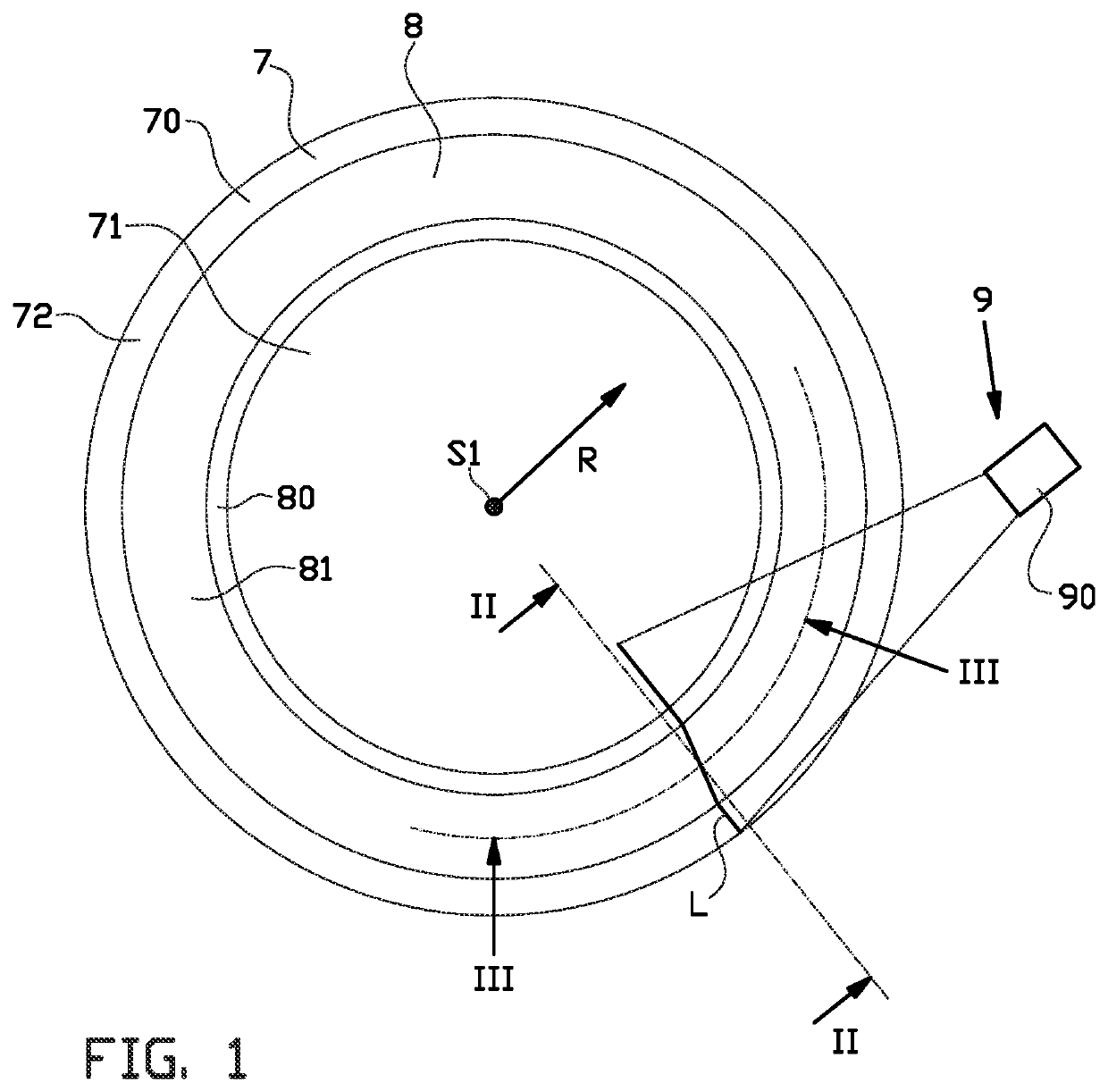
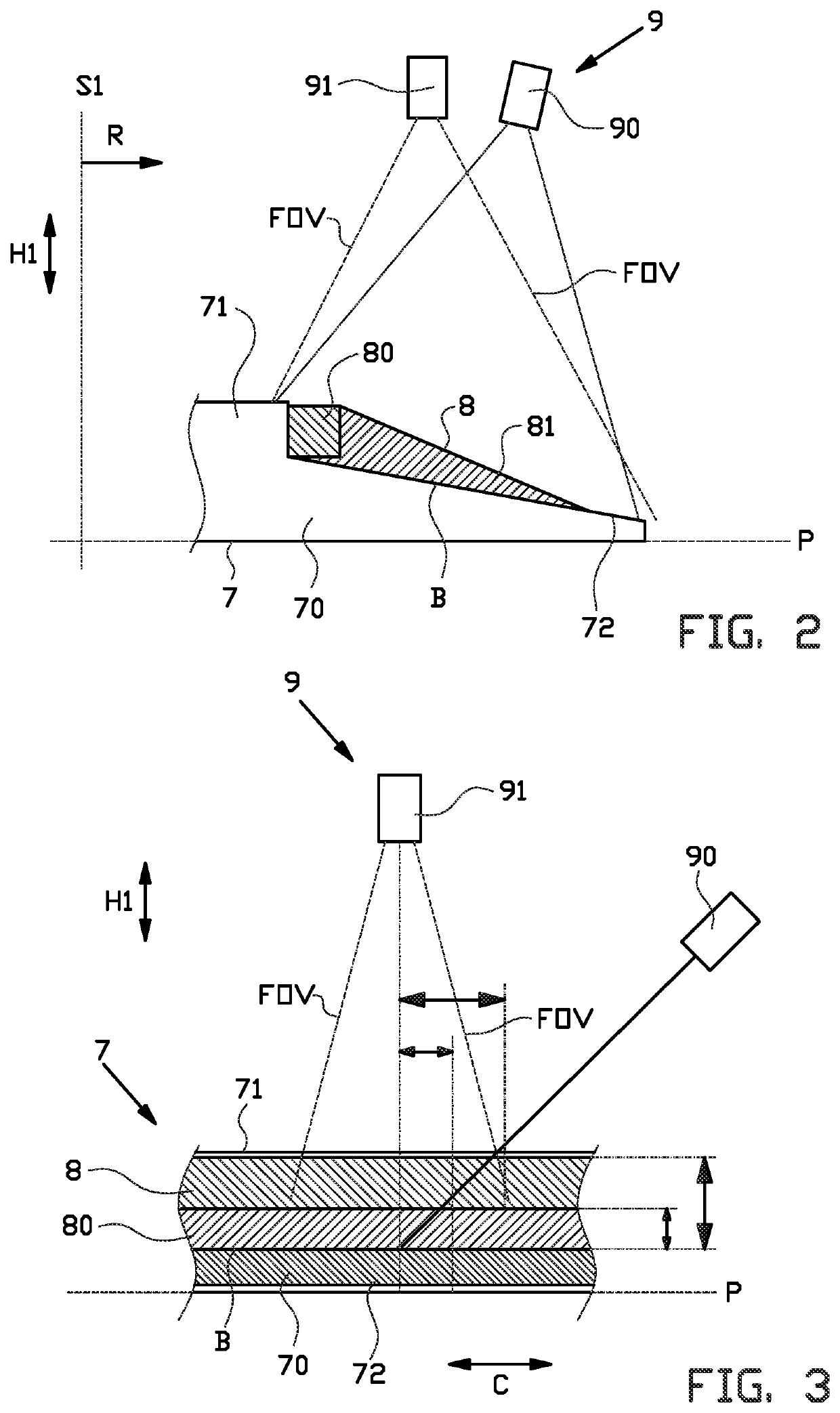
[0064]FIGS. 1, 2 and 3 show a bead-apex drum 7 for producing a bead-apex 8. In this exemplary embodiment, the bead-apex drum 7 is formed as a circular disc 70 having a central hub 71 and a bead-apex support surface 72 extending circumferentially about the central hub 71. The bead-apex drum 7 has a reference plane P, i.e. its mounting plane or its bottom surface, and a base profile B for supporting a bead-apex 8 relative to the reference plane P. The bead-apex drum 7 is typically mounted to a drum seat or drum drive (not shown) and driven in rotation about a rotation axis 51 extending concentrically through the central hub 71 in a direction perpendicular to the reference plane P.

[0065]A bead-apex 8 is formed by first applying a bead 80 on the bead-apex support surface 72 around the central hub 71 of the bead-apex drum 7, followed by an apex 81 that is applied around the bead 80. The bead-apex support surface 72 may be slightly angled to assume a conical orientation, i.e. at an obliqu...


PUM

PropertyMeasurementUnit
heightaaaaaaaaaa
heightsaaaaaaaaaa
oblique angleaaaaaaaaaa

Abstract

The invention relates to a calibration tool and a method for calibrating a laser-triangulation measuring system, wherein the calibration tool comprises a tool body that defines a reference plane and that is rotatable relative to the measuring system about a rotation axis perpendicular to said reference plane, wherein the tool body is provided with one or more calibration surfaces that define a pattern of calibration positions, wherein the pattern comprises at least three columns extending in a radial direction away from the rotation axis and at least three rows extending in a circumferential direction about the rotation axis, wherein for each column the calibration positions within said respective column vary in height relative to the reference plane in a height direction perpendicular to said reference plane and wherein for each row the calibration positions within the respective row vary in height in the height direction relative to the reference plane.

Description

BACKGROUND[0001]The invention relates to a calibration tool and a method for calibrating a measuring system, in particular a laser-triangulation measuring system.[0002]Measuring systems are used in the field of tire building during various stages of production to measure the quality and / or characteristics of one or more tire components. One of said stages is the production of a bead-apex. The bead-apex is formed by subsequently applying a bead and an apex around the circumference of a bead-apex drum. The bead-apex drum may receive beads and apexes in a wide variety of shapes and sizes. Moreover, the bead-apex drum also comes in various shapes and sizes and may be replaced by another bead-apex drum when appropriate. Finally, the part of the bead-apex drum that supports the apex is typically conical to support the apex at an oblique angle to the radial direction.SUMMARY OF THE INVENTION[0003]A disadvantage of the known laser-triangulation measuring system is that it may become inaccur...

Claims


Application Information

Patent Timeline
Patent Type & Authority Applications(United States)
IPC IPC(8): G01B11/25G01C11/30G01S7/497B29D30/00B29D30/24B29D30/26B29D30/32B29D30/48
CPCG01B11/2504G01C11/30G01S7/497B29D30/0061B29D2030/482B29D30/26B29D30/32B29D30/48B29D2030/3207B29D30/244G01C15/004G01B11/00G01C3/12G01M11/0264G01S17/48G06T7/80G06T7/521G01C11/02G01S17/88G01B11/022
Inventor KELLIJ, EGBERT GRIETINUSVAN DE VRUGT, JOHNTIELENBURG, NIELSVERBRUGGEN, TEUNIS JOHANNESBEEKMAN, PETERVAN VOSKUILEN, CEES JOHANNUSSELDER, ROBINBERGHORST, GERJAN ASUERUSVERLAAN, TITUS RUBENKOFOED, BARTBERGMANS, QUINTEN MATTHIJS
Owner VMI HOLLAND BV
Why Eureka
Eureka Blog
Learn More