
Dental object detection method, and image matching method and device using dental object

a technology of image matching and detection method, applied in the field of dental object detection method, image matching method and device using dental object, can solve the problems of reducing the speed of image registration, deteriorating detection time and efficiency, and frequent detection errors, so as to improve the accuracy of corresponding operations, improve detection time and efficiency, and increase usability

Pending Publication Date: 2022-05-26
DIO
View PDF0 Cites 0 Cited by
  • Summary
  • Abstract
  • Description
  • Claims
  • Application Information

AI Technical Summary

Benefits of technology

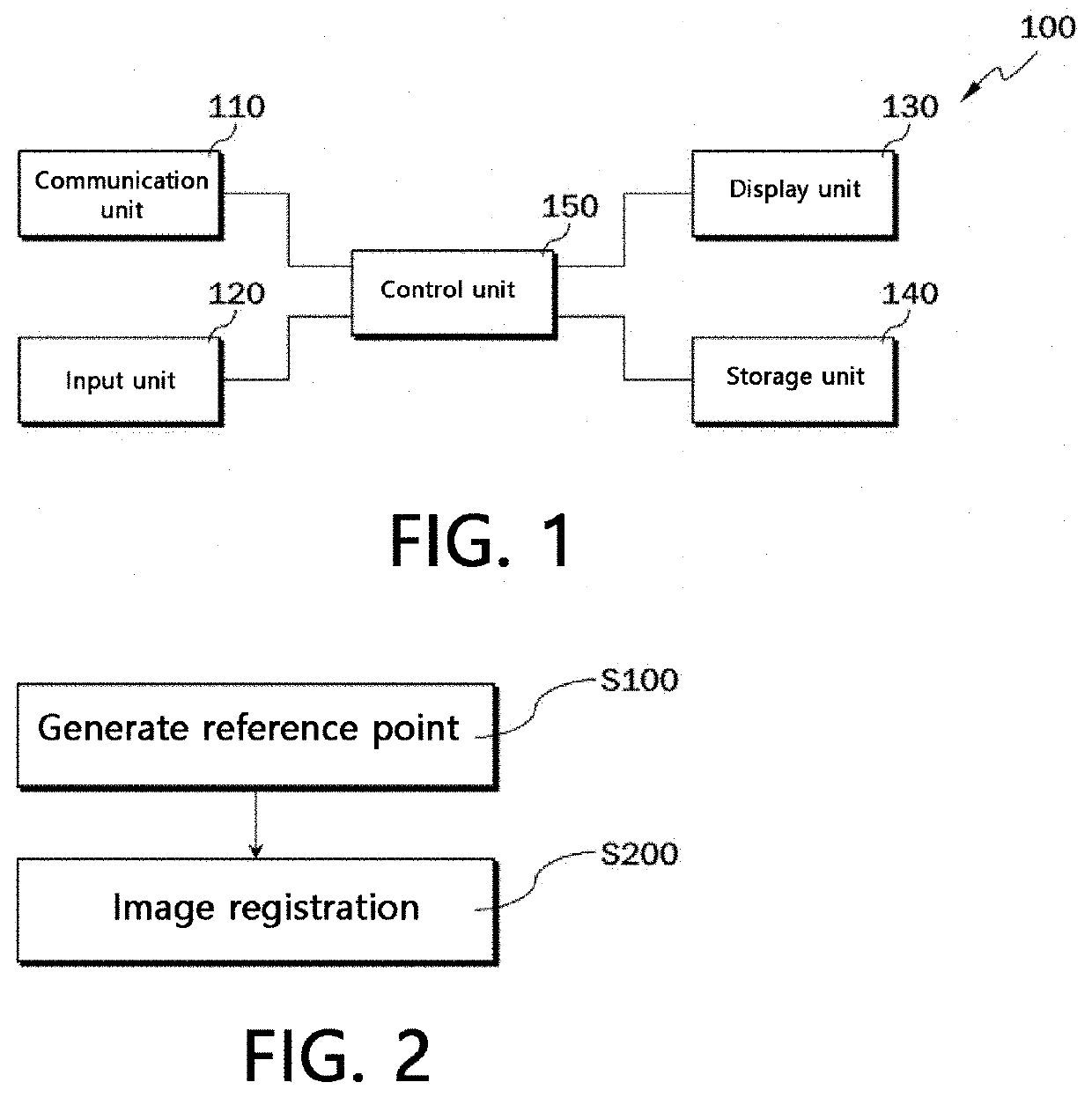
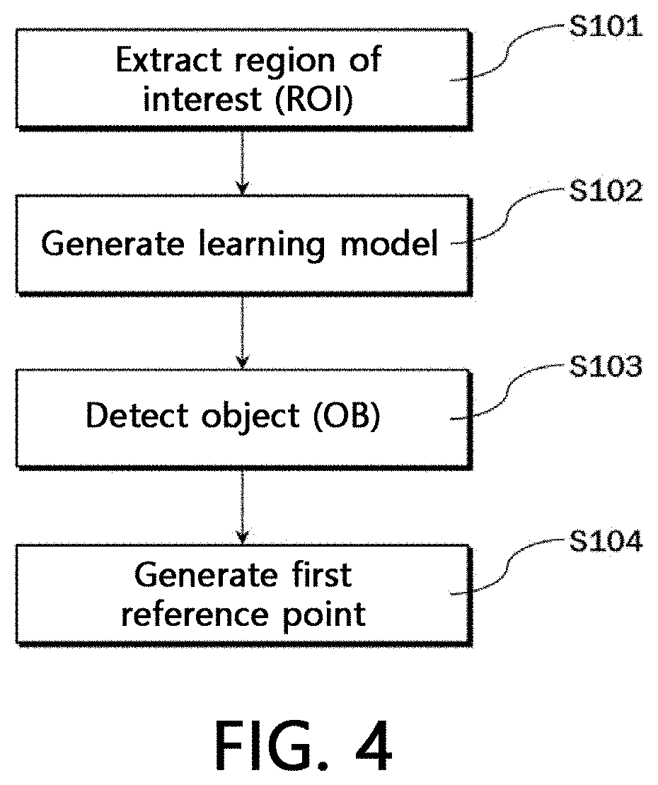
The present invention provides a method and apparatus for accurately and quickly registering images of teeth in an oral scan image and a CT image of the inside of the oral cavity using the objects of each tooth. This improves the detection of objects in the oral scan image and provides high-accuracy information on their location, center point, and size, which can be utilized for various dental procedures such as image registration with a CT image, identifying an implant placement position, and identifying a dental arch shape, etc. The invention also enhances the speed and accuracy of image registration by performing image registration between the oral scan image and the CT image using the object of each tooth that can be quickly and accurately extracted from the images.

Problems solved by technology

However, in such a conventional detection method, there was a problem in that have a problem in that the detection error occurs frequently because the boundary between the teeth is ambiguous and the curvature information of the tooth and the gum is similar, and the detection time and efficiency are deteriorated because the load according to the detection is large.
As a result, the conventional method has a problem in that not only the speed of image registration is reduced due to a large load, but also the image registration is inaccurate due to inaccurate characteristics of manual markers and vertexes.

Method used


Image

  • Dental object detection method, and image matching method and device using dental object
  • Dental object detection method, and image matching method and device using dental object
  • Dental object detection method, and image matching method and device using dental object

Examples


Embodiment Construction

[0044]The present invention and method of accomplishing the same may become more apparent through the following detailed description in relation to the accompanying drawings, and accordingly, those of ordinary skill in the art will be able to easily implement the technical idea of the present invention. In addition, in describing the present invention, when it is determined that a detailed description of a related known technology may unnecessarily obscure the subject matter of the present invention, the detailed description will be omitted.

[0045]The terms used in this specification are for the purpose of describing embodiments only and are not intended to be limiting to the present invention. In this specification, the singular form also includes the plural form in some cases, unless specifically specified in the phrase. In this specification, terms such as “include”, “comprise”, “provide” or “have” do not exclude the presence or addition of one or more other elements other than el...


PUM


Abstract

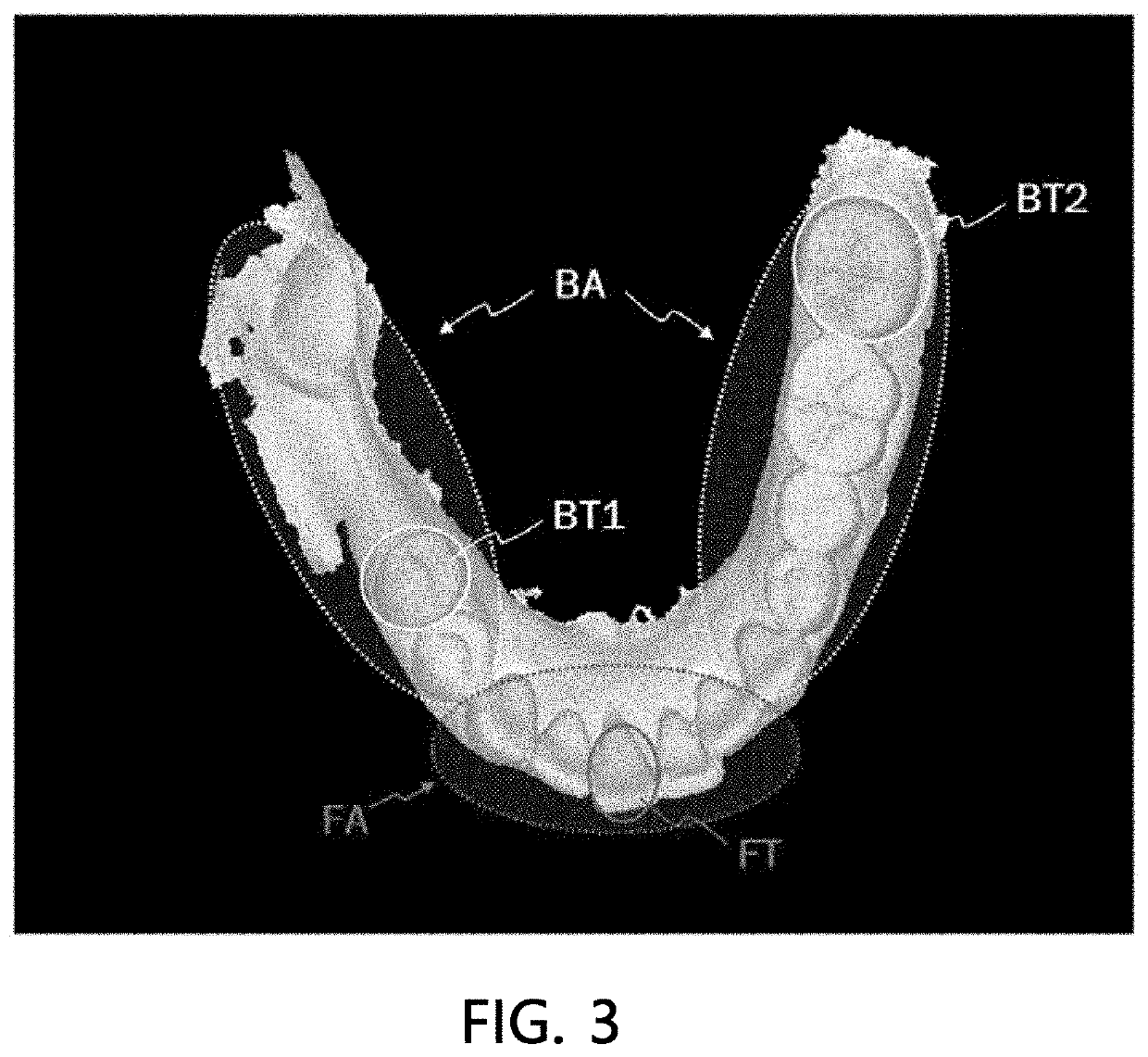
An image registration method using a dental object, comprises a generation step of generating a plurality of reference points spaced apart from each other in an oral scan image of a registration target and a computed tomography (CT) image of a registration target, respectively; and a step of registering the oral scan image of the registration target and the CT image of the registration target by using the reference point of the oral scan image (a first reference point) and the reference point of the CT image (a second reference point), wherein the first and second reference points comprise a reference point for one frontmost tooth in the front teeth area and a reference point for two teeth on both rearmost sides of the back teeth area, and wherein the first reference point is derived from an object which is a simplified shape of the teeth.

Description

CROSS-REFERENCE TO RELATED APPLICATION[0001]This application claims priority to and the benefit of Korean Patent Application Nos. 10-2019-0042382 and 10-2019-0042383, filed on Apr. 11, 2019, the disclosure of which is incorporated herein by reference in its entirety.BACKGROUND1. Field of the Invention[0002]The present invention relates to a method for detecting an object of each tooth in an oral scan image, and a method and apparatus capable of performing image registration between an oral scan image and a CT image using an object of each tooth in an oral scan image and a computed tomography (CT) image of the inside of the oral cavity.2. Discussion of Related Art[0003]In the field of dentistry, various procedures are performed using various images of the inside of the oral cavity. Such images include an oral scan image, a computed tomography (CT) image, and a magnetic resonance image (MRI). Among them, an oral scan image is a three-dimensional image that displays the surface state o...

Claims


Application Information

Patent Timeline
Patent Type & Authority Applications(United States)
IPC IPC(8): G06T7/00G06V10/25G06V20/50G06T7/70G06T7/60G06T7/30A61C9/00A61B6/03A61B6/14A61B6/51
CPCG06T7/0012G06V10/25G06V20/50G06T7/70G06T7/60G06T2207/10081A61C9/0053A61B6/032A61B6/14G06T2207/20081G06T2207/30036G06T7/30G06T7/33A61B2576/02A61B5/682A61B5/0088A61B5/0064A61B5/743A61B5/7485A61B2505/05A61B5/4547G06T2207/20084G06T2207/10028A61B6/51
Inventor KIM, JIN CHEOLKIM, JIN BAEK
Owner DIO
Learn More