Multilayer ceramic capacitor

a multi-layer ceramic and capacitor technology, applied in the direction of fixed capacitors, stacked capacitors, fixed capacitor details, etc., can solve the problems of reducing capacitance, voids likely to be generated in the internal electrodes after firing, and lowering the reliability of multi-layer ceramic capacitors

Pending Publication Date: 2022-05-26
MURATA MFG CO LTD
View PDF0 Cites 0 Cited by
  • Summary
  • Abstract
  • Description
  • Claims
  • Application Information

AI Technical Summary

Benefits of technology

[0051]As shown in FIG. 6, the second internal electrodes 32 include a fifth side E5 in the vicinity of the first side surface WS1, a sixth side E6 in the vicinity of the second side surface WS2, a seventh side E7 in the vicinity of the first end surface LS1, and an eighth side E8 in the vicinity of the second end surface LS2. The second internal electrodes 32 include a second outer peripheral portion 32A located in the vicinity of the three sides E5 to E7 except for the eighth side E8, which extends to the second end surface, among these four sides E5 to E8, and a second inner electrode portion 32B located inside the second outer peripheral portion 32A. The fifth side E5 to the eighth side E8 of the second internal electrodes 32 define the outer edge of the second internal electrodes 32.
[0052]The second inner electrode portion 32B includes a second opposing portion region 32B1 located in the second opposing portion 321, and a second lead-out portion region 32B2 located in the second lead-out portion 322. The second outer peripheral portion 32A includes a second opposing portion region 32A1 located in the second opposing portion 321, and a second lead-out portion region 32A2 located in the second lead-out portion 322. The second outer peripheral portion 32A may also be divided as follows. That is, the second outer peripheral portion 32A may include a first side surface-side region 32AW1 located in the vicinity of the first side surface WS1, a second side surface-side region 32AW2 located in the vicinity of the second side surface WS2, and a first end surface-side region 32AL1 located in the vicinity of the first end surface LS1.
[0053]A length L2 in the length direction connecting the first end surface LS1 and the second end surface LS2, of the first end surface-side region 32AL1 of the second outer peripheral portion 32A is preferably, for example, about 5% or more and about 10% or less of a length L1 connecting the seventh side E7 in the vicinity of the first end surface LS1 and the eighth side E8 in the vicinity of the second end surface LS2 of the second internal electrodes 32. A length W2 in the width direction connecting the first side surface WS1 and the second side surface WS2 of the first side surface-side region 32AW1 of the second outer peripheral portion 32A is preferably, for example, about 5% or more and about 20% or less

Problems solved by technology

However, when the internal electrodes are thinned, voids are likely to be generated in the internal electrodes after firing.
Therefore, a problem occurs in that the capacitance decreases due to a decrease in the active area contributing to the ge

Method used


Image

  • Multilayer ceramic capacitor
  • Multilayer ceramic capacitor
  • Multilayer ceramic capacitor

Examples


experimental examples

[0163]According to the above-described non-limiting example of a manufacturing method, a multilayer ceramic capacitor of the experimental example shown in FIG. 12 was manufactured, and the measurement of the capacitance and the test of the reliability were performed. FIG. 12 provides schematic diagrams each showing the shape of an internal electrode in the experimental examples.

[0164]First, in order to produce samples of the experimental examples, multilayer ceramic capacitors having the following specifications were produced in accordance with the above-described manufacturing method.

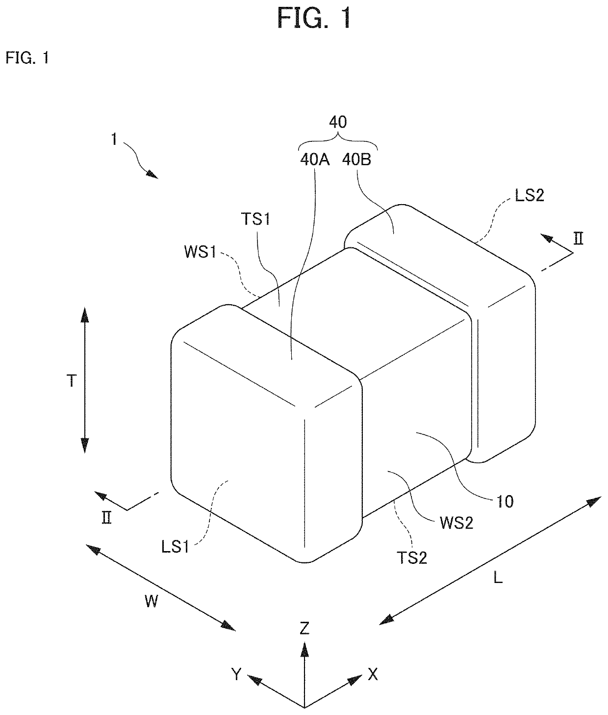
[0165]Dimensions of multilayer ceramic capacitors: L×W×T=about 2.2 mm×about 1.4 mm×about 0.8 mm

[0166]Dielectric layer: BaTiO3

[0167]Relative dielectric constant A3 of the first dielectric layer in the first high dielectric constant portion: about 3800

[0168]Relative dielectric constant B3 of the first dielectric layer in the first inner dielectric layer portion: about 3000

[0169]Relative dielectric const...


PUM

PropertyMeasurementUnit
Lengthaaaaaaaaaa
Lengthaaaaaaaaaa
Lengthaaaaaaaaaa

Abstract

A multilayer ceramic capacitor includes a first internal electrode, a second internal electrode, a first dielectric layer, and a second dielectric layer. The first internal electrode includes a first outer peripheral portion and a first inner electrode portion inside the first outer peripheral portion. The second internal electrode includes a second outer peripheral portion and a second inner electrode portion inside the second outer peripheral portion. The first dielectric layer includes a first high dielectric constant portion, and a first inner dielectric layer portion inside the first high dielectric constant portion. The second dielectric layer include a second high dielectric constant portion and a second inner dielectric layer portion inside the second high dielectric constant portion.

Description

CROSS REFERENCE TO RELATED APPLICATIONS[0001]This application claims the benefit of priority to Japanese Patent Application No. 2020-195387 filed on Nov. 25, 2020. The entire contents of this application are hereby incorporated herein by reference.BACKGROUND OF THE INVENTION1. Field of the Invention[0002]The present invention relates to a multilayer ceramic capacitor.2. Description of the Related Art[0003]Conventionally, multilayer ceramic capacitors have been known. In general, a multilayer ceramic capacitor includes a ceramic sintered body made of a dielectric ceramic such as barium titanate. Inside the ceramic sintered body, a plurality of internal electrodes are laminated with ceramic layers interposed therebetween. Furthermore, external electrodes are respectively provided on one end surface and on the other end surface of this ceramic sintered body such that the external electrodes are respectively connected to the internal electrodes (for example, refer to Japanese Unexamined...

Claims


Application Information

Patent Timeline
IPC IPC(8): H01G4/12H01G4/30
CPCH01G4/1209H01G4/30H01G4/12H01G4/005H01G4/012H01G4/1227H01G4/1236H01G4/0085H01G4/224
Inventor NISHIKORI, MAKOTO
Owner MURATA MFG CO LTD
Why Eureka
Try Eureka