Glazing unit with frequency selective coating and method

Pending Publication Date: 2022-06-09
AGC GLASS EUROPE +3
View PDF0 Cites 0 Cited by
  • Summary
  • Abstract
  • Description
  • Claims
  • Application Information

AI Technical Summary

Benefits of technology

[0014]It is an object of the present invention to alleviate these problems and especially the outdoor to indoor and/or the indoor to outdoor penetration, and to provide a glazing unit capable, in some configurations, of

Problems solved by technology

Such coating systems, however, are typically electrically conductive and are high in reflectance for RF radiation.
This effect impedes reception or transmission by antennas.
The result is that many newer constructions severely impede RF

Method used


Image

  • Glazing unit with frequency selective coating and method
  • Glazing unit with frequency selective coating and method
  • Glazing unit with frequency selective coating and method

Examples


Example

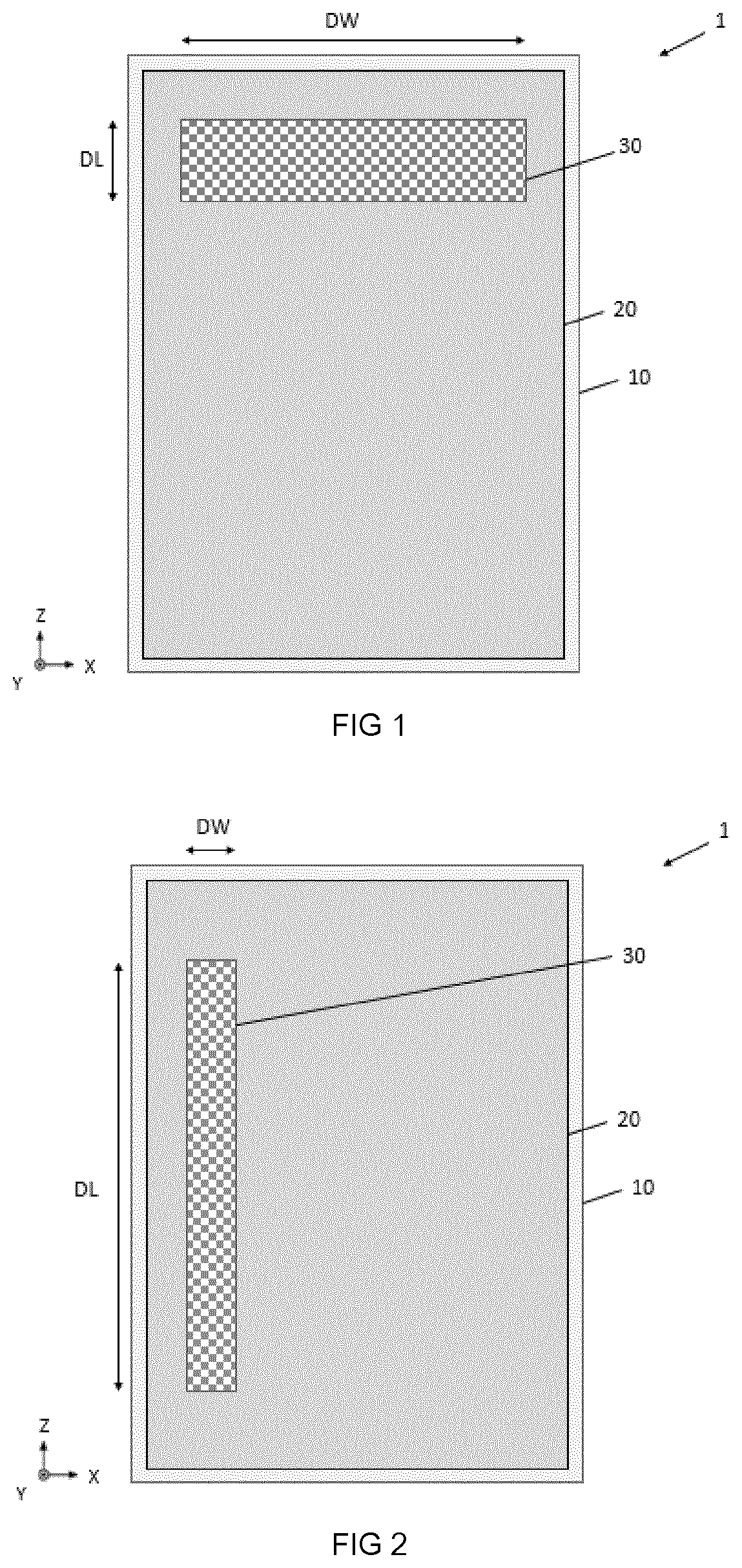
[0093]With reference to FIG. 1, a first embodiment of the present invention is described.

[0094]As shown in FIG. 1, a glazing unit 1 comprises a glass panel 10 which is low in reflectance for RF radiation, a coating system 20 which is high in reflectance for RF radiation disposed on the said glass panel. The glazing unit further comprises at least one frequencies selective decoated portion 30 of the coating system extending along a plane, P, defined by a longitudinal axis, X, and a vertical axis, Z; having a width, DW, measured along the longitudinal axis, X, and a length, DL, measured along the vertical axis, Z.

[0095]FIG. 1 shows a rectangular shape frequencies selective decoated portion 30 of the coating system. This shape can be different for example, a square, a circle, a polygon, . . . depending of the desired application.

[0096]In FIG. 1, the rectangular shape frequencies selective decoated portion 30 of the coating system is placed on the top part of the glazing unit.

[0097]FIG....


PUM

PropertyMeasurementUnit
Temperatureaaaaaaaaaa
Fractionaaaaaaaaaa
Fractionaaaaaaaaaa

Abstract

An improved glazing unit including a glass panel which is low in reflectance for RF radiation, a coating system which is high in reflectance for RF radiation disposed on the glass panel and creating onto the glazing unit a dual band bandpass filter. The glazing unit further includes at least one frequencies selective decoated portion of the coating system extending along a plane, P; having a width, DW, and a length, DL. The at least one frequencies selective decoated portion features a first decoated element with a plurality of unit cells, and a plurality of second decoated elements where a second decoated element is placed in a unit cell of the first decoated element, but no second decoated element is in contact with the first decoated element and at least one unit cell of the first decoated element has no second decoated element.

Description

TECHNICAL FIELD[0001]The present invention relates to a glazing unit with frequency selective coating.BACKGROUND ART[0002]The invention is concerned generally with provision of a surface on a coated glass panel, which has frequency selective transmission characteristics and, in some embodiments, to providing such a surface on glazing sheets having a coating system such as a solar control coating deposited thereon.[0003]In glazing for buildings and automotive applications, antennas for reception and, or transmission of radio frequency (RF) waves are commonly incorporated. These may be realised as, for example, conductive films deposited on the glazing or metal wires or strips attached thereto. In laminated glazings, which typically comprise two or more glass sheets bonded by a polymer interlayer, the antennas might be located within the laminate i.e. within the interlayer or on a glass surface contacting the interlayer.[0004]In addition, in many cases additional equipment is operated...

Claims


Application Information

Patent Timeline
IPC IPC(8): C03C17/36B23K26/362B23K26/402
CPCC03C17/366C03C17/3644C03C17/3649B23K26/362B23K26/402B23K2101/34C03C2217/231C03C2217/256C03C2217/253C03C2217/252C03C2217/948C03C2218/328B32B17/10192H01Q1/44H01Q1/1271H01Q15/0013B23K26/359B23K26/364C03C17/36B23K26/355B23K2103/54B23K26/0006B32B17/10119B32B17/10761B32B17/10788B32B17/10229B32B17/10211
Inventor LEMOINE, ADRIEN
Owner AGC GLASS EUROPE
Why Eureka
Try Eureka