
Clutch mechanism with dual clutch devices and a planetary gearset

Inactive Publication Date: 2006-02-16
HONDA MOTOR CO LTD
View PDF6 Cites 0 Cited by
  • Summary
  • Abstract
  • Description
  • Claims
  • Application Information

AI Technical Summary

Benefits of technology

[0014] Accordingly, one object of this invention is to provide a clutch mechanism that can replace a torque converter in use with an automotive automatic transmission.
[0015] Another object of this invention is to provide a clutch mechanism that can be used both for starting and also to double the number of effective gear ratios in the transmission.
[0017] One advantage of this invention is that by replacing the conventional torque converter with the inventive clutch mechanism automatic transmission inefficiency is greatly improved.
[0018] Another advantage of this invention is that the number of effective gear ratios available in the transmission can be doubled.

Problems solved by technology

Torque converters, however, have disadvantages.
One disadvantage is that torque converters are known to be relatively inefficient.
In particular, torque converters generally provide relatively poor fuel economy—although this can be improved with the addition of a lockup clutch.
However, Smith does not provide a gear splitting feature for use in doubling the number of gear ratios supplied by the transmission.
However, Hayashi et al. does not provide a single transmission input shaft separately rotatable by either clutch independently.
However, Janson does not provide a single transmission input shaft separately rotatable by either clutch independently.
However, this solution has the disadvantage of adding undesirable weight and cost to the manufacture of a transmission.

Method used


Image

  • Clutch mechanism with dual clutch devices and a planetary gearset
  • Clutch mechanism with dual clutch devices and a planetary gearset
  • Clutch mechanism with dual clutch devices and a planetary gearset

Examples


Embodiment Construction

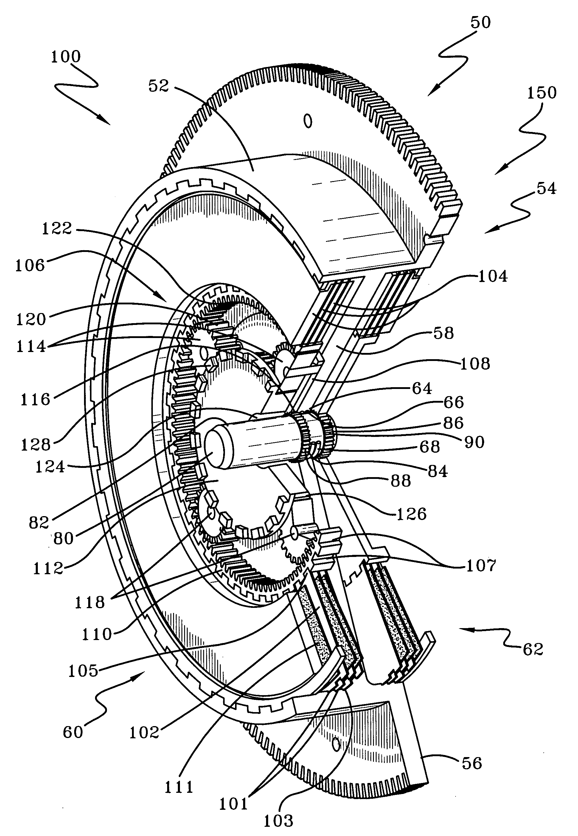
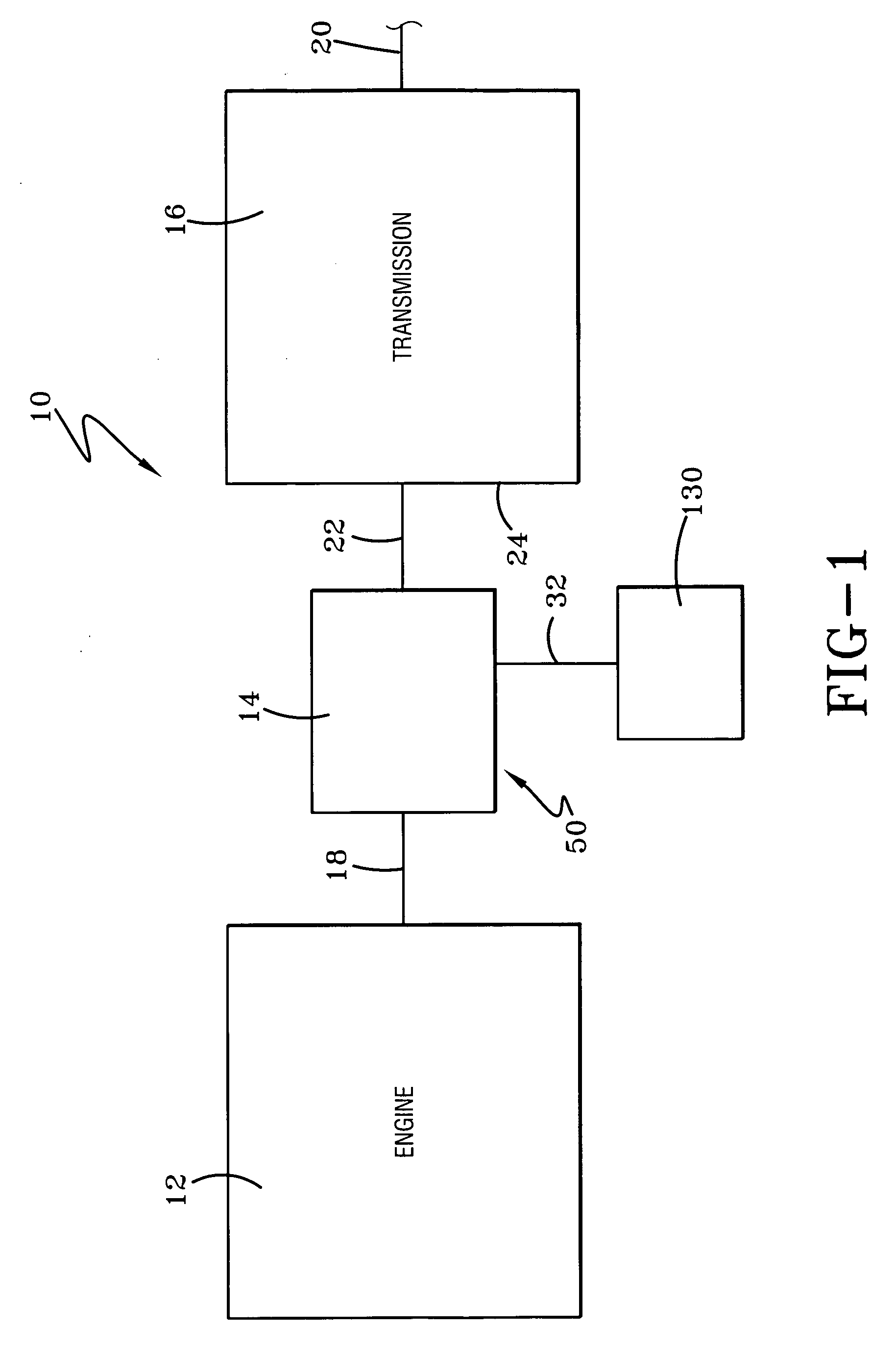
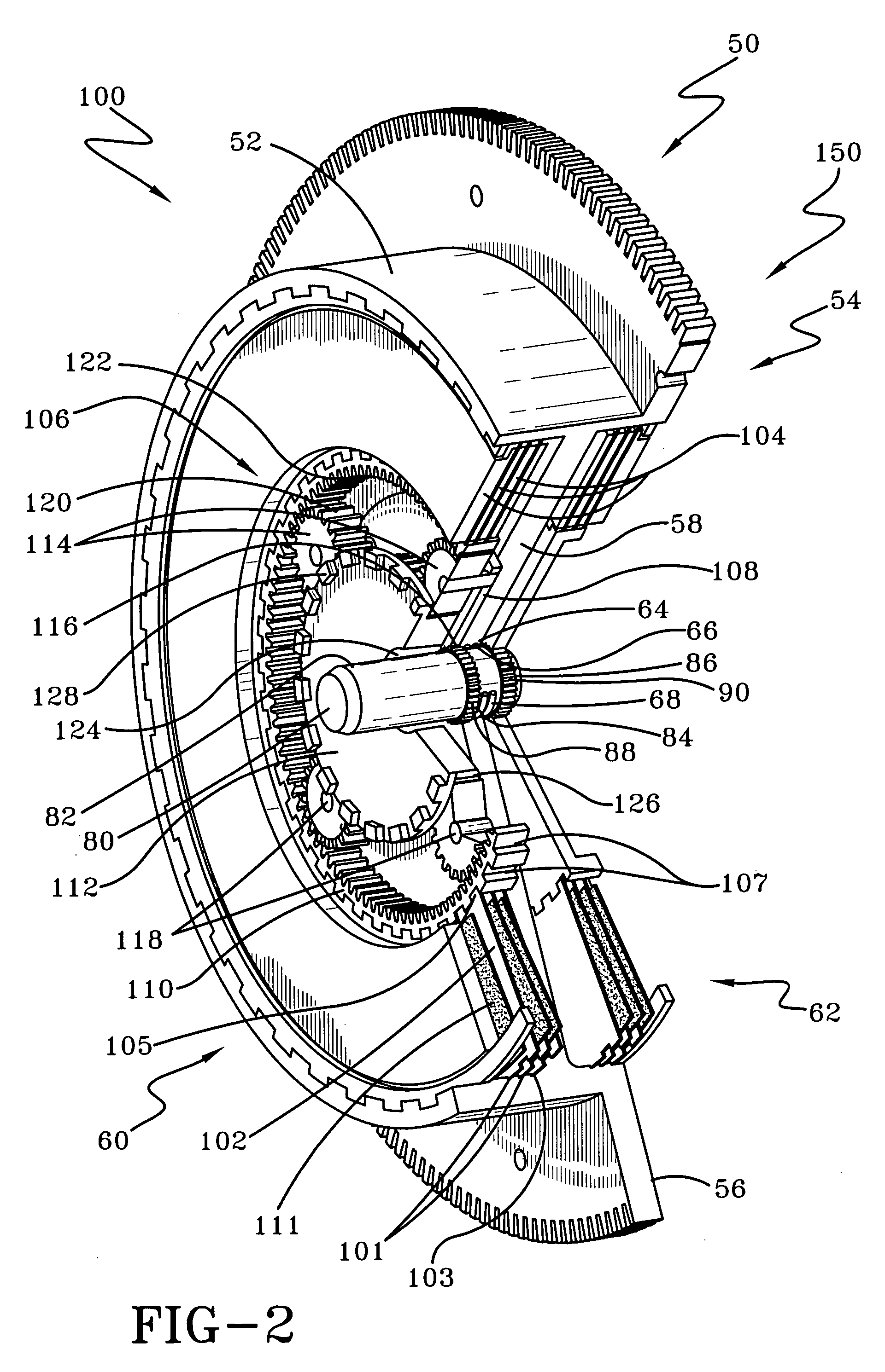
[0024] Referring now to the drawings wherein the showings are for purposes of illustrating a preferred embodiment of the invention only and not for purposes of limiting the same, FIG. 1 illustrates some of the primary components of a drive system 10 for use with a vehicle such as an automobile. In particular, FIG. 1 shows an engine 12, a conversion device 14 and a transmission 16. As is well known in the art, the transmission 16 permits the engine 12 to operate in a relatively narrow speed range while providing a wide range of output speeds. The transmission 16 includes a plurality of gears (not shown) in order to make effective use of the engine's 12 torque and provide a number of gear ratios for use in driving (providing locomotion to) the automobile. The engine 12 drives (rotates) a drive shaft 18 in order to provide torque for the transmission 16. The transmission has an output, transmission output shaft 20, that is used to transfer torque from the transmission 16 to the automob...


PUM


Abstract

A clutch mechanism includes a housing adapted to be rotated by an automotive engine, a shaft having first and second sections and a first end adapted to be an input to a transmission, and first and second clutch devices positioned with the housing. The first clutch device, which includes a planetary gear set, can be connected to the first section of the shaft to rotate the shaft. The second clutch device can be connected to the second section of the shaft to rotate the shaft. The planetary gear set provides a gear splitting system for use in doubling the number of gear ratios supplied by the transmission.

Description

I. BACKGROUND OF THE INVENTION [0001] A. Field of the Invention [0002] This invention pertains to apparatuses and methods regarding a clutch mechanism that can replace a torque converter and more specifically to apparatuses and methods regarding a clutch mechanism using a pair of clutches that provides a starting clutch and a gear splitting feature for use in doubling the number of gear ratios supplied by an automatic transmission. [0003] B. Related Background Art [0004] The use of a torque converter between an automotive engine and an automatic transmission is well known in the art. Torque converters are fluid couplings that permit the engine drive shaft to rotate somewhat independently of the automatic transmission. As a result, torque converters permit the automobile to start motion and also to come to a complete stop without stalling the engine. Torque converters thus work well for their intended purpose. [0005] Torque converters, however, have disadvantages. One disadvantage is...

Claims


Application Information

Patent Timeline
IPC IPC(8): F16H3/44
CPCF16H3/54F16D25/0638
Inventor SKILES, RANDYBURKE, BOBBIEDICKINSON, MICHAEL
Owner HONDA MOTOR CO LTD
Learn More