Impregnation device for trickle impregnation of a stator of an electric machine

a technology of impregnation device and stator, which is applied in the manufacture of dynamo-electric machines, dynamo-electric machines, electrical apparatus, etc., can solve the problems of only knowing the temperature of synthetic resin, complicated and complicated feeding of current to the rotating stator or armature, etc., and achieve uniform and rapid heating of the stator

Pending Publication Date: 2022-06-09
GEHRING E TECH GMBH
View PDF0 Cites 0 Cited by
  • Summary
  • Abstract
  • Description
  • Claims
  • Application Information

AI Technical Summary

Benefits of technology

[0014]According to a preferred further development of the impregnation device according to the invention, it is provided that the at least one temperature sensor is arranged on the drive shaft, by means of which sensor the temperature on the radial inner face of the stator core and / or the winding can be measured. The drive shaft provides sufficient installation space for the arrangement of the at least one temperature sensor. In addition, this drive shaft, equipped with the at least one temperature sensor, is pushed axially into the relevant stator in order to grasp and hold it and is later removed again together with the temperature sensor attached thereto. Thus, one or more of the temperature sensors need not be attached to the radial inner peripheral surface of each individual stator to be impregnated.
[0015]It is particularly advantageous if a temperature sensor in the region of the axial center of the stator and in each case a temperature sensor in the region of the axial end of the stator or the winding heads formed there are arranged on the drive shaft. By means of these three temperature sensors, an axial heating profile can be determined, which allows a control device to recognize at which axial regions of the stator its heating needs to be intensified at the expense of other axial regions. For this purpose, the control device will vary the axial back and forth movement of the inductor and / or the current intensity passed through it in order to achieve uniform and rapid heating of the stator.

Problems solved by technology

However, the disadvantage of these known methods and the devices used for impregnating a stator or armature of an electric machine is that the temperature control is carried out by means of a heating current passed through the winding, and it is technically complicated to feed this current to the rotating stator or armature.
In addition, the methods and devices proposed in the two publications have the defect that the heating current controls are turned off solely based on the temperature of the winding through which the heating current flows.
This is unfavorable at least in those periods in which the other components surrounding the windings have not yet assumed the temperature of the windings.
However, because the synthetic resin makes contact, not only between adjacent wires or wire portions of the windings, but also with other components of the stator or armature, the temperature there is not precisely known for the synthetic resin.
Because this uncertainty regarding the temperatures of the components of the stator or armature and the synthetic resin is also present at the beginning of the curing process, this process must also be extended disadvantageously for a safety period.
Lastly, it is disadvantageous that the heating of the synthetic resin takes place only indirectly through heat transfer between the windings and the resin.
This means that reaching the trickle temperature and the curing temperature takes a comparatively long time.
The described time periods for the impregnation of a stator or armature result in a costly prolongation of the production time and an increase in energy costs for heating up to and maintaining the trickle and curing temperatures.
The difficulty arose here that the stator rotates about its longitudinal axis during the trickle impregnation process.

Method used


Image

  • Impregnation device for trickle impregnation of a stator of an electric machine

Examples


Embodiment Construction

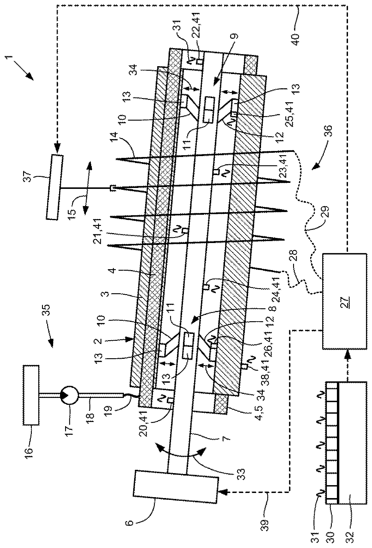
[0022]Accordingly, the FIGURE shows an impregnation device 1 for a hollow cylindrical stator 2. The stator 2 to be treated in the impregnation device 1 is, after its final completion, a component of an electric machine, for example an electric motor or a generator. The stator 2 has, for example, a conventional structure with annularly arranged stator segments, each of these stator segments having a frame to which lamination plates arranged one behind the other are fastened. The frame and the stator lamination plates together form a stator core 3. Stator windings 4 made up of wires or conductor bars are arranged between adjacent stator segments, the line ends of which are routed out of the stator core 3 in the region of a winding head 5 on the axial end. In addition, insulation material (not shown) is arranged in the stator 2, by means of which insulation material, components to be electrically separated from one another are spaced apart from one another.

[0023]The stator 2 is accommo...


PUM

PropertyMeasurementUnit
temperatureaaaaaaaaaa

Abstract

The invention relates to an impregnation device for trickle impregnation of a stator of an electric machine with a synthetic resin which cures under an increase in temperature, the stator having a hollow cylindrical stator core and at least one winding, a drive shaft being arranged coaxially inside the stator and being drivable by a drive motor, at least one holding device being arranged on the drive shaft, by means of which holding device the stator can be detachably connected to the drive shaft.

Description

[0001]The invention relates to an impregnation device for trickle impregnation of a stator of an electric machine with a synthetic resin which cures under an increase in temperature, the stator having a hollow cylindrical stator core and at least one winding, a drive shaft being arranged coaxially inside the stator and being drivable by a drive motor, at least one holding device being arranged on the drive shaft, by means of which holding device the stator can be detachably connected to the drive shaft, wherein a trickle device is provided, by means of which the synthetic resin can be directed onto at least one axial end of the winding of the stator, wherein a heating device is provided, by means of which the winding and the stator core can be heated to a predetermined trickle temperature, and the heating device having at least one electromagnetic inductor which is arranged so as to be movable coaxially or axially parallel to the stator.[0002]It is generally known that in the manufa...

Claims


Application Information

Patent Timeline
Patent Type & Authority Applications(United States)
IPC IPC(8): H02K15/12B29C39/44B29C39/10
CPCH02K15/12B29L2031/749B29C39/10B29C39/44B05B13/0228B05C5/0241B05C9/14B05C13/02
Inventor BERTHOLD, JENSRASP, RICHARD A.
Owner GEHRING E TECH GMBH
Why Eureka
Try Eureka