
Door lock, device for controlling door lock, program for controlling door lock and server f or managing door lock

a door lock and door lock technology, applied in the field of door locks, can solve the problems of limiting access to a specific security area, inconvenience of re-setting passwords or keys, and affecting the security of the property owner

Pending Publication Date: 2022-06-30
PSDL
View PDF0 Cites 0 Cited by
  • Summary
  • Abstract
  • Description
  • Claims
  • Application Information

AI Technical Summary

Benefits of technology

The present invention provides a door lock with strong security and ease of use. The invention also includes a control device, program, and management server for the door lock. The door lock can improve user convenience and can determine whether to allow access anytime, anywhere without restrictions on time and place. Users can easily collect information on the door lock and release the lock setting of the corresponding door lock through a simple operation of tagging the door lock. Overall, the invention avoids the risk of hacking and provides a more efficient and user-friendly door lock system.

Problems solved by technology

However, when the stay period has elapsed, the landlord has the inconvenience of having to re-set the password or key every time after moving out.
Meanwhile, in the case of a company or institution where security is important, access to a specific security area is restricted according to an individual security level.

Method used


Image

  • Door lock, device for controlling door lock, program for controlling door lock and server f or managing door lock
  • Door lock, device for controlling door lock, program for controlling door lock and server f or managing door lock
  • Door lock, device for controlling door lock, program for controlling door lock and server f or managing door lock

Examples


first embodiment

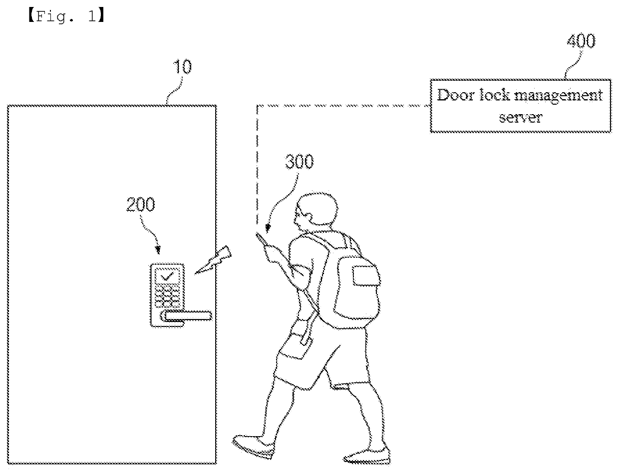
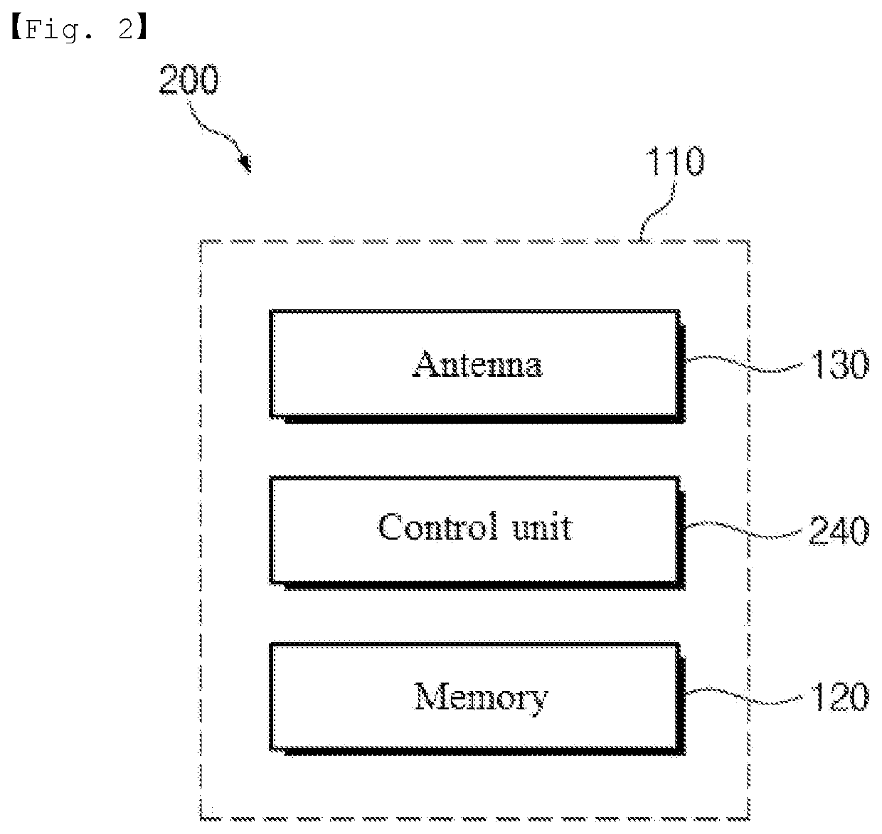
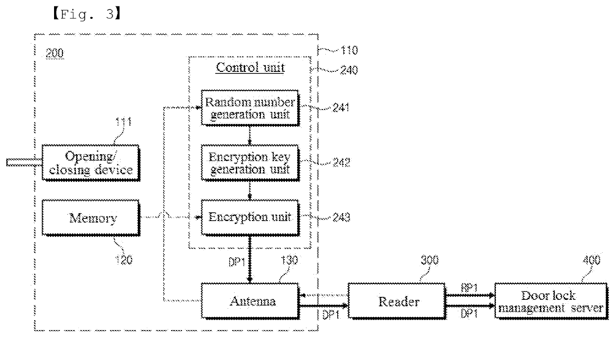
[0079]Hereinafter, a door lock according to the present invention will be described with reference to FIGS. 2 to 4.

[0080]FIG. 2 is a block diagram illustrating a door lock according to a first embodiment of the present invention. FIGS. and 4 are reference diagrams illustrating the flow of information when a door lock according to the first embodiment of the present invention is tagged by a reader.

[0081]Referring to FIG. 2, the door lock 200 according to the first embodiment of the present invention, which is installed in the entrance / exit door 10 provided in an accommodation facility, a toilet of a building, an office, an entrance / exit control areas, etc., may include a door lock body 110, a memory 120, an antenna 130 and a control unit 240.

[0082]The door lock body 110 forms the external appearance of the door lock 200. The door lock body 110 is installed in the door 10, and may include an outer body installed outside the door 10 and an inner body installed inside the door 10. The d...

second embodiment

[0186]Hereinafter, a process of unlocking the door lock according to the present invention will be described chronologically with reference to FIGS. 15 and 16.

[0187]In this case, the second embodiment of the present invention is different from the first embodiment of the present invention only in the encryption scheme, and since the components are the same, a detailed description of the same components will be omitted.

[0188]As an operation proceeding operation S41, an operation of provisioning the master private encryption key (Priv_m) may be performed. This may mean that the same master private encryption key (Priv_m) is stored in the memory 120 of the door lock 200 and the door lock management server 400 as described above. This may be performed at an initial setting stage, for example at factory shipment. In this document, the master private encryption key (Priv_m) and the master public encryption key (Pub_server) may be understood as encryption keys corresponding to the server p...

third embodiment

[0232]Hereinafter, a process of unlocking the door lock according to the present invention will be described chronologically with reference to FIGS. 17 and 18.

[0233]In this case, the third embodiment of the present invention is different from the first embodiment of the present invention only in the encryption scheme, and since the components are the same, a detailed description of the same components will be omitted.

[0234]As an operation preceding operation S41, an operation of provisioning a server public encryption key (Pub_Server) may be performed. As described above, this may mean that the same server public encryption key (Pub_Server) is stored in the memory 120 of the door lock 200 and the door lock management server 400, which may be performed at an initial setting stage, for example, when being released from a factory.

[0235]Referring to FIG. 17, when a door recognition code is requested from the reader 300 through an RF signal in operation S41, the door lock 200 may generat...


PUM


Abstract

Provided is a door lock. The door lock includes a door lock body installed on a door and having an opening / closing device for opening and closing the door; a memory embedded in the door lock body to store a door lock identifier including a door recognition code assigned to the door and a door lock ID matched with the door recognition code; an antenna provided in the door lock body to sequentially receive a first RF signal and a second RF signal from a reader; and a control unit configured to transmit the door recognition code to the reader through the antenna such that the door recognition code together with a reader recognition code previously assigned to the reader is authenticated by a door lock management server that is communicatively connected with the reader when receiving the first RF signal, and configured to determine whether the door lock ID provided from the door lock management server through the reader matches the previously assigned door lock ID of the door lock identifier when receiving the second RF signal to control the opening / closing device such that the door is maintained in a lock state or released from the lock state.

Description

CROSS-REFERENCE TO RELATED APPLICATIONS[0001]This application claims the priority of the Korean Patent Applications NO 10-2020-0187897 filed on Dec. 30, 2020, in the Korean Intellectual Property Office, the disclosure of which is incorporated herein by reference.BACKGROUND OF THE INVENTION1. Field of the Invention[0002]The present invention relates to a door lock, a device for controlling the door lock, a program for controlling the door lock, and a server for managing the door lock, and more particularly, to a door lock having a strong security function, a device for controlling the door lock, a program for controlling the door lock, and a server for managing the door lock.2. Description of the Related Art[0003]In recent years, in order to block the intrusion of outsiders who are not permitted to enter the door of a place such as a house, apartment, or office, and for easy entry and exit of insiders, most conventional locks are being replaced with digital door locks.[0004]Meanwhile...

Claims


Application Information

Patent Timeline
IPC IPC(8): G07C9/00H04L9/08H04L9/30
CPCG07C9/00817G07C9/00571G07C9/00904G07C2009/00412H04L9/088H04L9/30G07C9/00309H04L9/0866H04L2209/805H04L9/0841H04W12/71H04W12/069H04L9/0825H04L9/0869G07C2009/005E05B2047/0067
Inventor CHUN, SUNGWOOHWANG, DEOK SOO
Owner PSDL
Learn More