Supercharge Your Innovation With Domain-Expert AI Agents!

Footwear with a composite plate sole assembly

a composite plate and sole assembly technology, applied in the field of footwear, can solve the problems of typical poor execution, too narrow, side parts of the plate to become too flexible,

Pending Publication Date: 2022-07-07
SAUCONY
View PDF0 Cites 0 Cited by
  • Summary
  • Abstract
  • Description
  • Claims
  • Application Information

AI Technical Summary

Benefits of technology

The present invention is a shoe construction that improves energy return and gait efficiency. It takes a plate with multiple radii and stages them to provide a smooth transition and more spring and energy return to the foot during toe off. This shoe construction can make the wearer's foot more efficient in running activities, from sprints to marathons. It also includes mounting caps for attaching traction spikes, flexibility for different terrains, and stability and support for the foot.

Problems solved by technology

This type of slit can enhance the side to side flexibility of the plate, however, it typically is not executed well.
Frequently, the slit is too narrow, and the plate to the left and right of the slit extends too far forwardly under all the toes of a wearer.
As a result, the tips of the plate can become worn out and crack, and / or the slit can cause the side parts of the plate to become too flexible, and not flexing in unison, which can throw the gait of the user.
Another issue with current composite plates is that they typically are uniformly rigid.
For outdoor performance shoes and hiking boots having a particularly rigid composite plate, this can be problematic because it can inhibit upward bendability of the footwear during toe off when climbing a hill or other terrain.
Conversely, if the plate is too bendable, it will not offer adequate support when the footwear engages rocks or hard terrain.

Method used


Image

  • Footwear with a composite plate sole assembly
  • Footwear with a composite plate sole assembly
  • Footwear with a composite plate sole assembly

Examples


Embodiment Construction

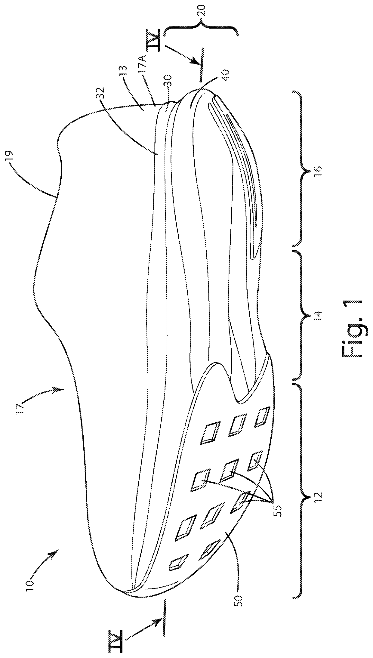
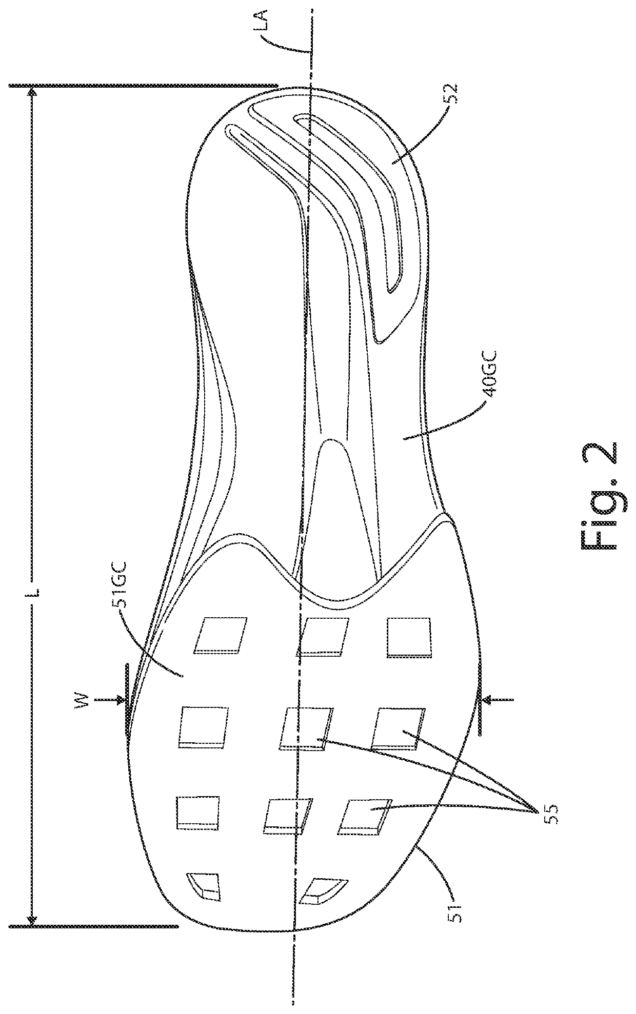
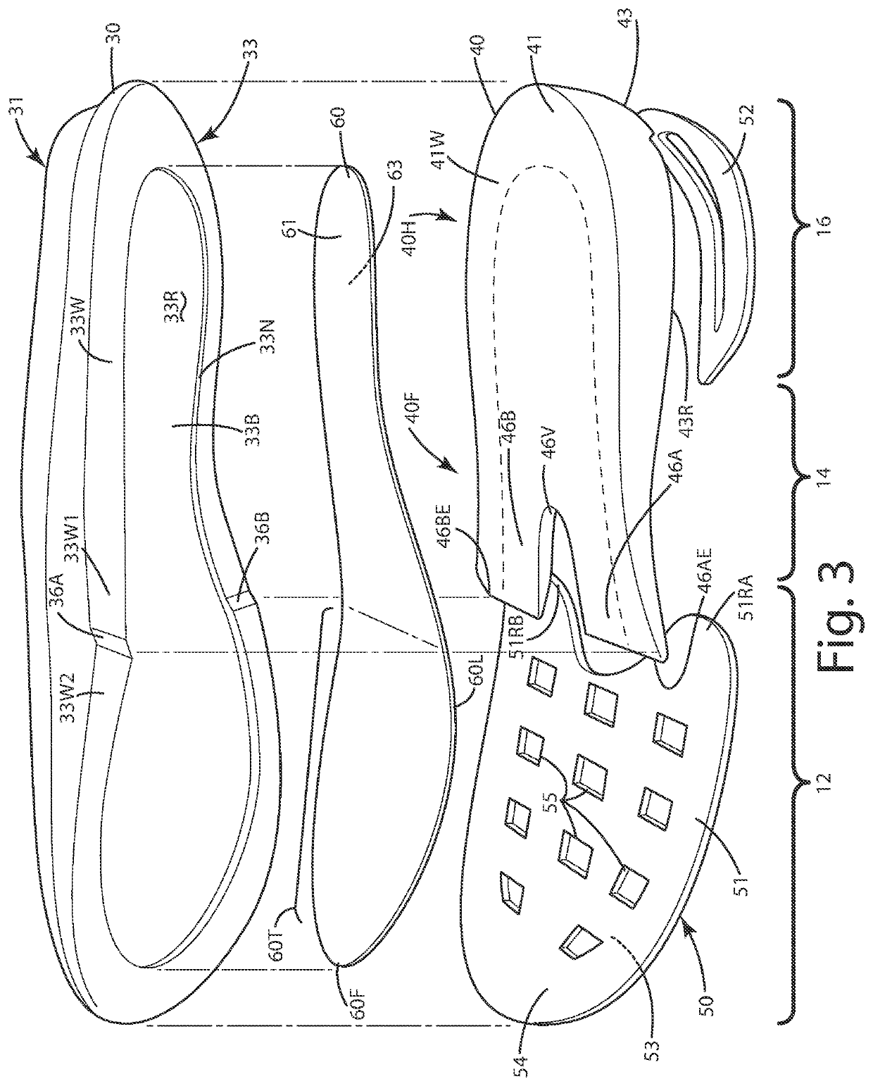
[0049]A current embodiment of the footwear is illustrated in FIGS. 1-4 and generally designated 10. In this embodiment, the footwear includes a sole assembly 20 including a first midsole platform 30, a second midsole platform 40, a plate 60 therebetween and an outsole layer 50 having multiple treads in the forefoot region of the footwear, where the plate is directly above and engaging the outsole layer. Although the current embodiment is illustrated in the context of a running shoe, the sole assembly thereof can be incorporated into any type or style of footwear, including performance shoes, trail shoes and boots, work boots, all-terrain shoes, hiking shoes, athletic shoes, running shoes, sneakers, conventional tennis shoes, walking shoes, multisport footwear, casual shoes, dress shoes or any other type of footwear or footwear components. It also should be noted that directional terms, such as “vertical,”“horizontal,”“top,”“bottom,”“upper,”“lower,”“inner,”“inwardly,”“outer” and “out...


PUM


Abstract

A footwear construction includes a sole assembly including a first midsole, a second midsole, a spring plate between the first and second midsoles, and an outsole. The plate can include an upward curving, multi-radii transition portion extending from a lowermost portion to a forward most portion of the plate so as to roll a wearer's foot forward into a next stride in a gait cycle of the wearer. The plate can include a lateral arm and a medial arm in the forefoot region separated by a plate slot extending rearward from the forwardmost portion of the plate toward the lowermost portion. The medial arm can be longer than the lateral arm. The plate can have a first bending stiffness during bending in a first direction, and a second bending stiffness greater than the first bending stiffness during bending in a second direction.

Description

CROSS REFERENCE TO RELATED APPLICATIONS[0001]This application is a continuation in part of patent application Ser. No. 16 / 927,269 filed Jul. 13, 2020, entitled FOOTWEAR WITH A COMPOSITE PLATE SOLE ASSEMBLY, which claims priority to provisional application Ser. No. 62 / 884,301, filed Aug. 8, 2019 entitled FOOTWEAR WITH A COMPOSITE PLATE SOLE ASSEMBLY.BACKGROUND OF THE INVENTION[0002]The present invention relates to footwear, and more particularly to footwear including a sole assembly having a composite plate that cooperates with an outsole to provide enhanced stability, traction and improved energy return to a wearer.[0003]There is a variety of different types of sole assemblies used in conjunction with footwear. Many sole assemblies include a midsole constructed from foam and an underlying outsole, usually constructed from rubber for durability. The foam provides underfoot cushion, and the outsole can include lugs for traction and wear resistance. Some sole assemblies also can includ...

Claims


Application Information

Patent Timeline
Patent Type & Authority Applications(United States)
IPC IPC(8): A43B13/12
CPCA43B13/127A43B13/026A43B13/185A43B13/141A43B13/26
Inventor PAULSON, ANDREA A.MAHONEY, CHRISTOPHER J.THERRIAULT, BRIAN D.PLAINTE, ERIC P.
Owner SAUCONY
Features
  • R&D
  • Intellectual Property
  • Life Sciences
  • Materials
  • Tech Scout
  • Unparalleled Data Quality
  • Higher Quality Content
  • 60% Fewer Hallucinations
Learn More