
Generator with torsional damper

a technology of torsional damper and generator, which is applied in the direction of vibration suppression adjustment, mechanical energy handling, mechanical apparatus, etc., can solve the problem that the generator may experience sustained torsional vibration

Active Publication Date: 2022-07-14
HAMILTON SUNDSTRAND CORP
View PDF4 Cites 2 Cited by
  • Summary
  • Abstract
  • Description
  • Claims
  • Application Information

AI Technical Summary

Benefits of technology

The patent describes a rotor assembly for an electric machine that includes a hydraulic damper sleeve between the main rotor shaft and center drive shaft. The hydraulic damper sleeve has cavities that allow fluid to enter and exit, damping the movement between the shafts. The assembly also includes flow restrictors that control the fluid flow. This design prevents damage and ensures smooth operation of the electric machine.

Problems solved by technology

In some operating conditions, a generator may experience a sustained torsional vibration.

Method used


Image

  • Generator with torsional damper
  • Generator with torsional damper
  • Generator with torsional damper

Examples


Embodiment Construction

[0035]A detailed description of one or more embodiments of the disclosed apparatus and method are presented herein by way of exemplification and not limitation with reference to the Figures.

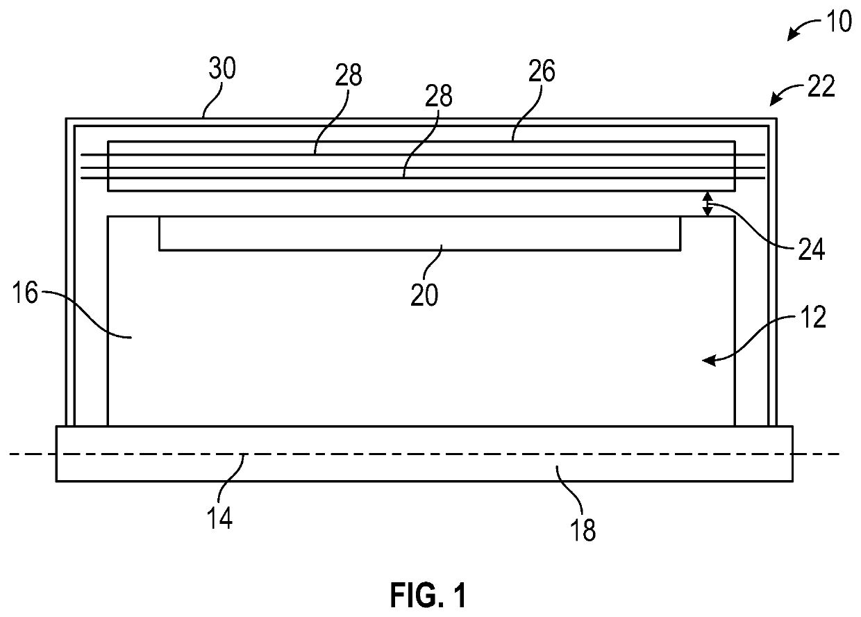
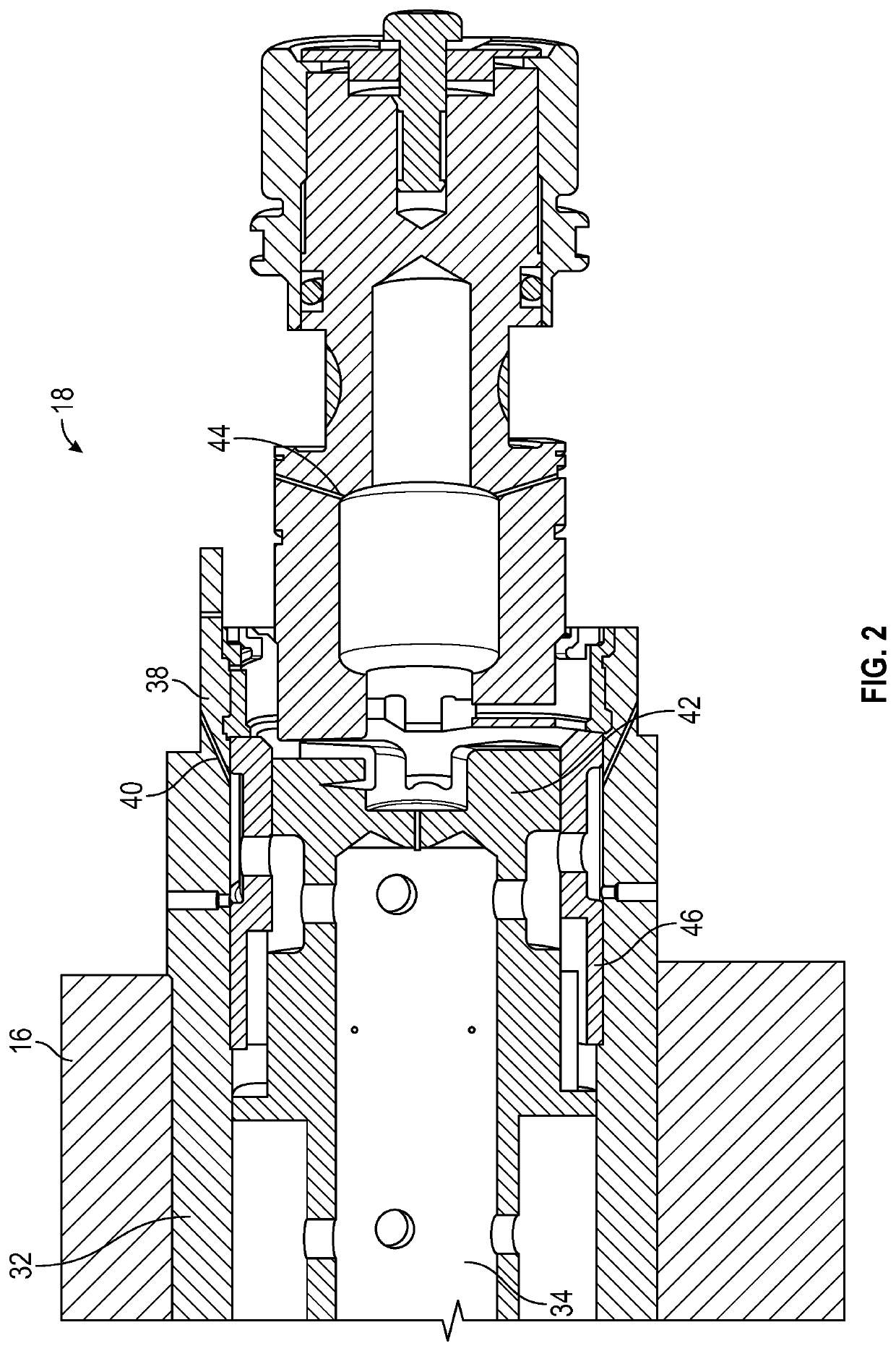
[0036]Referring now to FIG. 1, illustrated is a schematic view of an embodiment of an electric machine 10. The electric machine 10 includes a rotor assembly 12 configured to rotate about a machine central axis 14. In some embodiments, the rotor assembly 12 includes a rotor body 16, and a rotor shaft assembly 18 located at the machine central axis 14. In some embodiments, the electric machine 10 is a permanent magnet electric machine with a plurality of permanent magnets 20 located at the rotor body 16. In other embodiments (not illustrated), the electric machine 10 is a wound field electric machine with a plurality of rotor coils located at the rotor body. A stator 22 is located radially outboard of the rotor assembly 12 defining a radial air gap 24 between the stator 22 and the rotor assembly 12...


PUM


Abstract

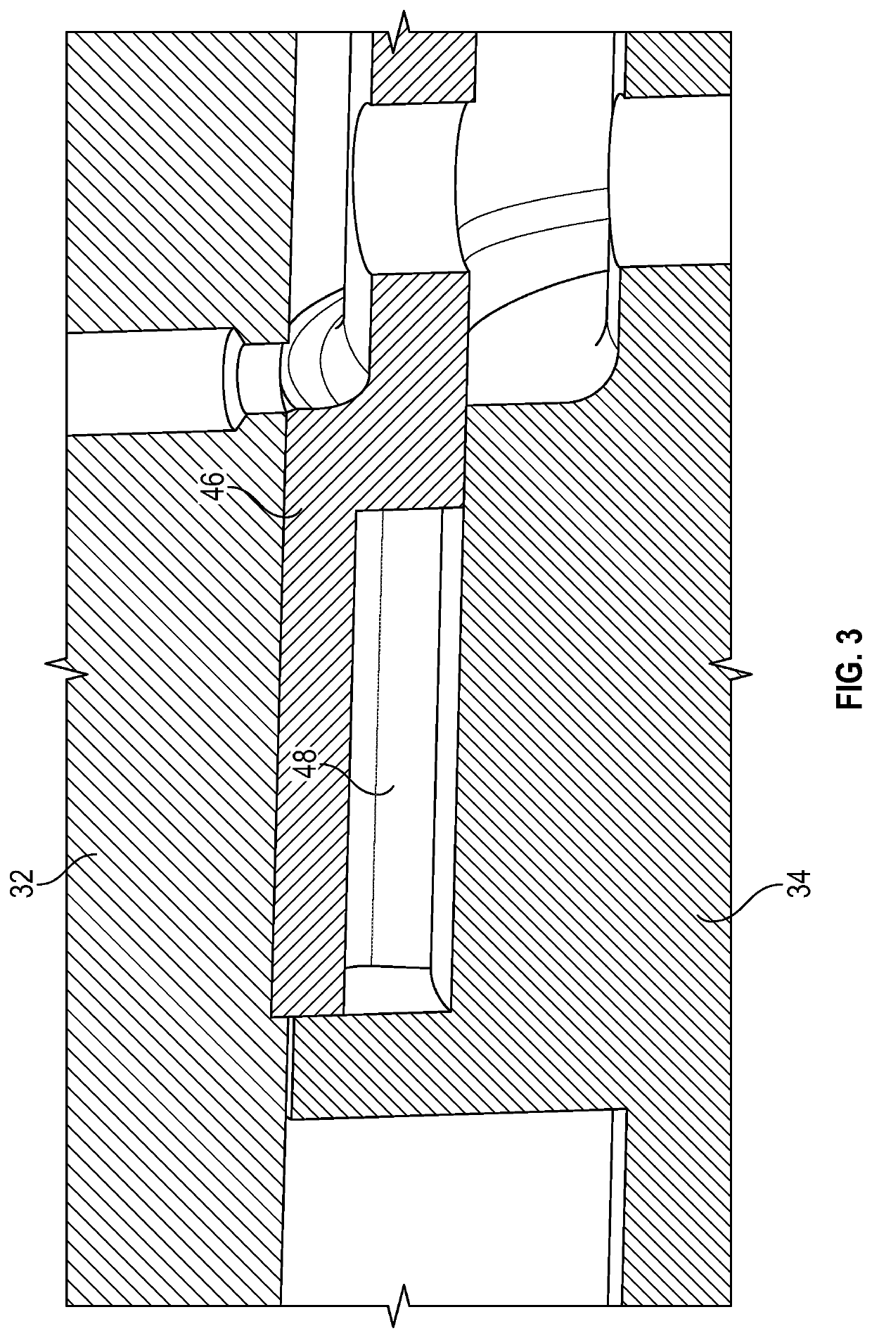
A rotor assembly of an electric machine includes a rotor body and a shaft assembly positioned at a central axis of the rotor assembly, and operably connected thereto. The shaft assembly includes a main rotor shaft operably connected to the rotor body, a center drive shaft located inside of the main rotor shaft, and a hydraulic damper sleeve located radially between the main rotor shaft and the center drive shaft. The hydraulic damper sleeve defines a plurality of cavities between the hydraulic damper sleeve and the center drive shaft. The hydraulic damper sleeve is configured to urge a fluid into and out of the plurality of cavities thereby damping relative circumferential motion between the main rotor shaft and the center drive shaft. A plurality of flow restrictors are configured to easily allow fluid into the plurality of cavities, while restricting flow of fluid out of the plurality of cavities.

Description

BACKGROUND[0001]Exemplary embodiments pertain to the art of electrical power generators for, for example, aircraft.[0002]Aircraft require electrical power for systems such as avionics, flight controls, passenger comfort and various other systems. The necessary electrical power is typically generated by engine-driven generators and by auxiliary power unit (APU) driven generators.[0003]In some operating conditions, a generator may experience a sustained torsional vibration. This torsional vibration, when combined with a spring rate of a center drive shaft of the generator, causes a relative velocity to be generated between a main rotor shaft of the generator and the center drive shaft nested inside of the main rotor shaft.BRIEF DESCRIPTION[0004]In one embodiment, a rotor assembly of an electric machine includes a rotor body and a shaft assembly positioned at a central axis of the rotor assembly, and operably connected to the rotor body. The shaft assembly includes a main rotor shaft o...

Claims


Application Information

Patent Timeline
Patent Type & Authority Applications(United States)
IPC IPC(8): H02K5/24H02K7/14H02K5/124
CPCH02K5/24H02K5/124H02K7/14H02K7/10F16F15/161
Inventor HIMMELMANN, RICHARD A.
Owner HAMILTON SUNDSTRAND CORP
Learn More