Supercharge Your Innovation With Domain-Expert AI Agents!

Virtual 3D display apparatus

Pending Publication Date: 2022-07-14
LEE CARSON WAI KEUNG
View PDF0 Cites 0 Cited by
  • Summary
  • Abstract
  • Description
  • Claims
  • Application Information

AI Technical Summary

Benefits of technology

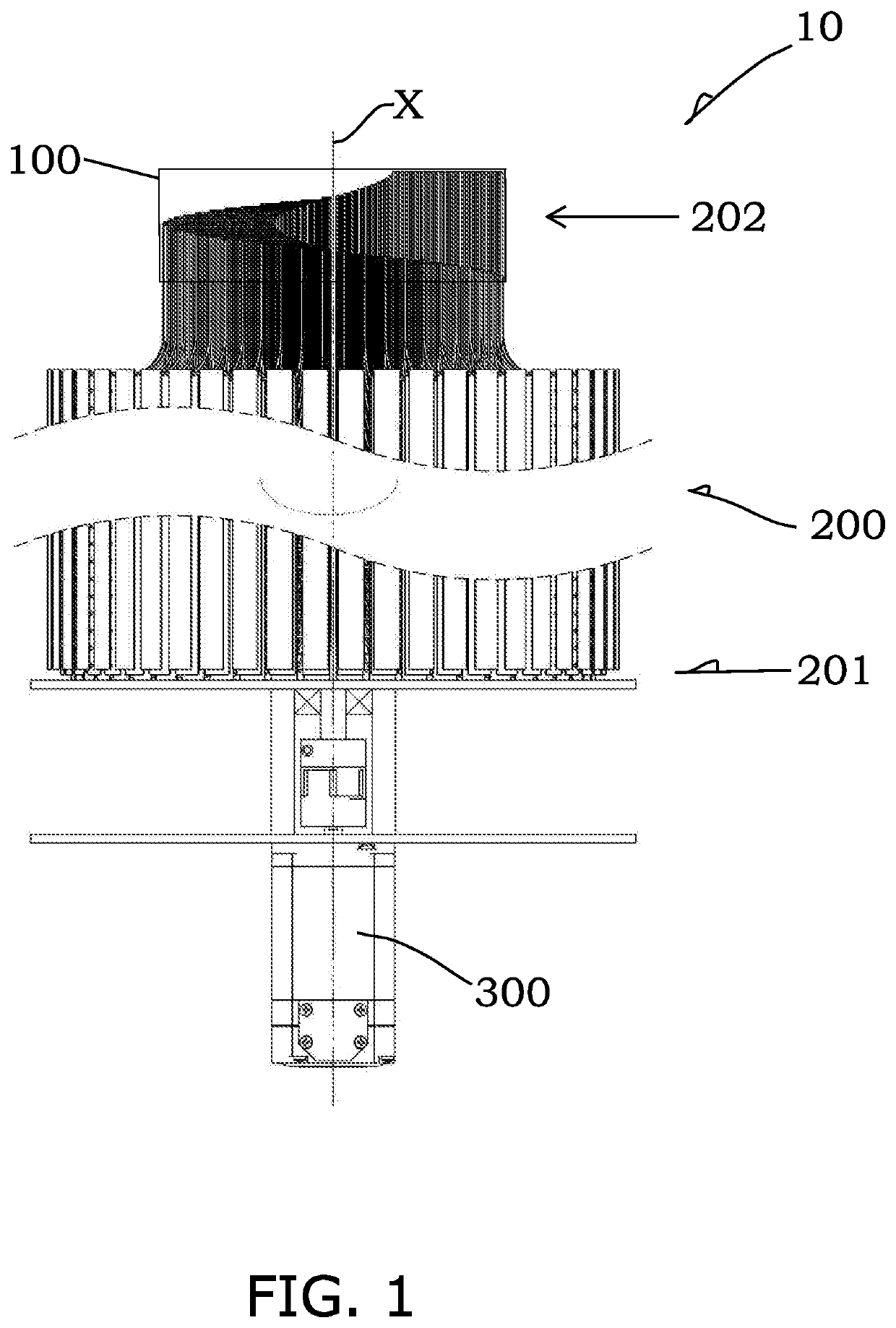
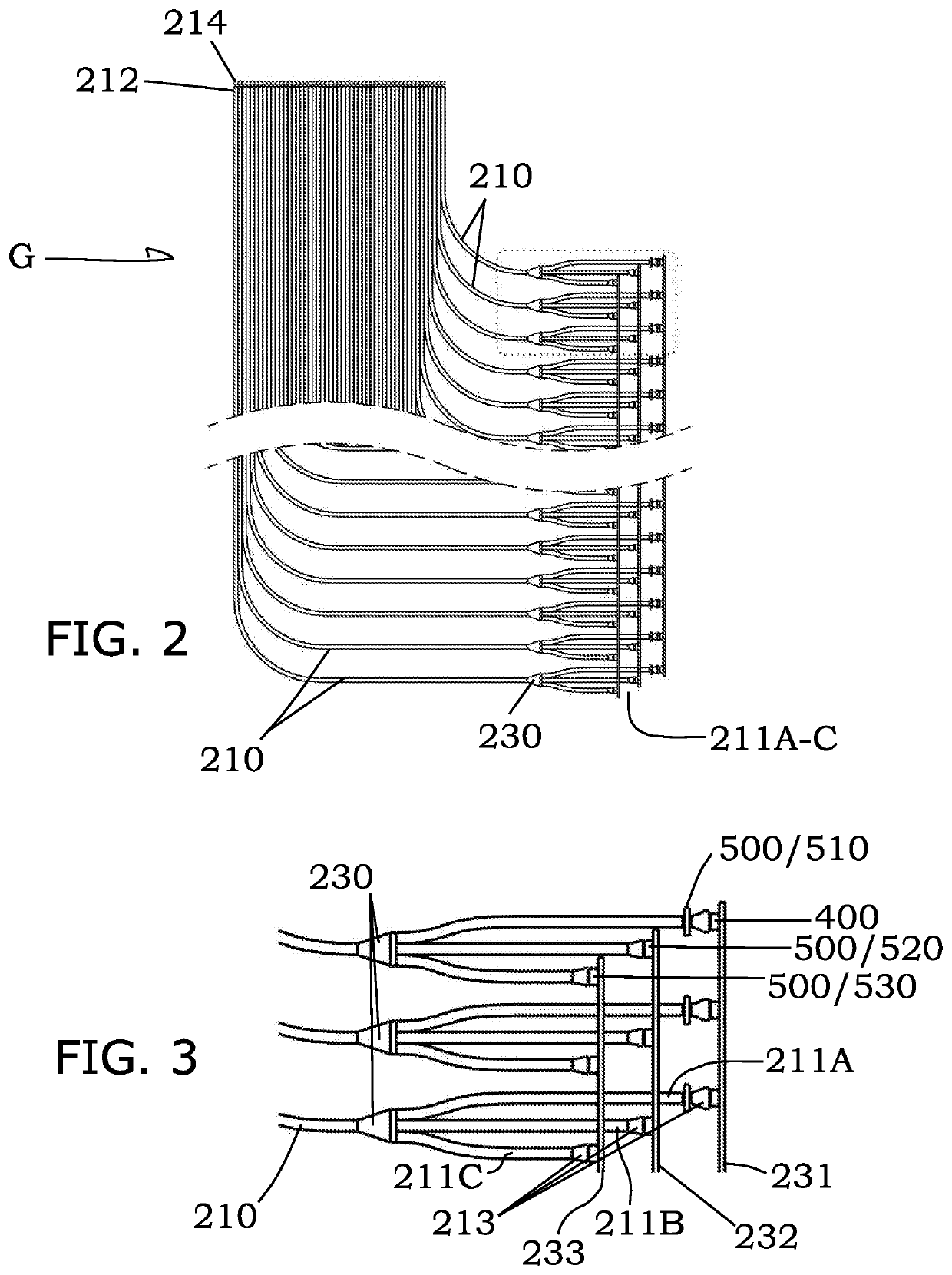
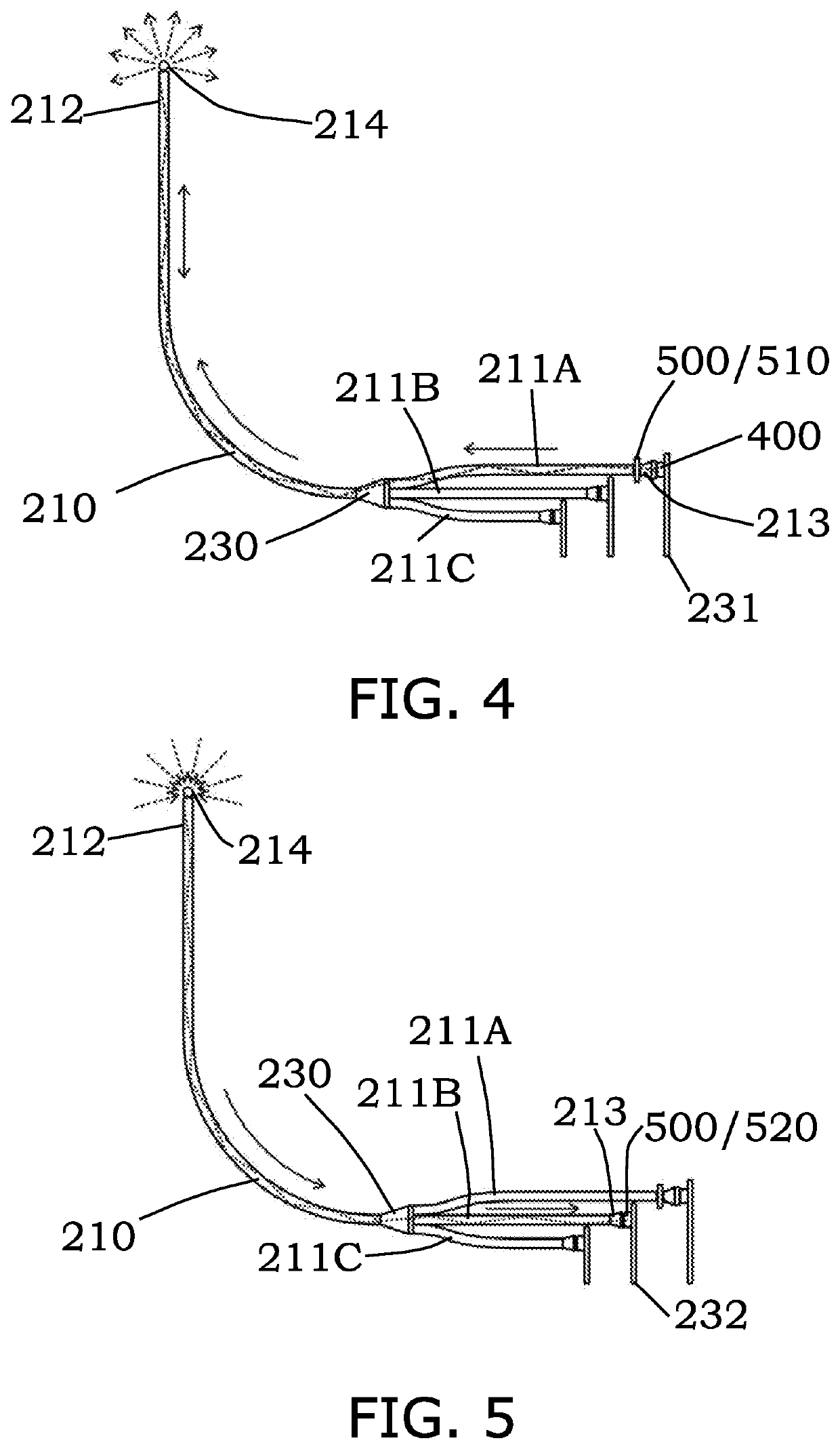
The invention is a virtual 3D display apparatus that uses optical fibers to create a virtual 3D image. The apparatus includes an optical fiber assembly with multiple optical fibers and a prime mover for driving the assembly in motion. The optical fibers have input and output ends, and a plurality of light sources and control elements. The control elements can adjust the virtual 3D image based on control signals that travel along the optical fibers. The optical fibers are divided into groups, with the output ends arranged in a sequence for lateral movement across the display zone to form different parts of the virtual 3D image. The optical fibers can be in a curved or flat plane configuration, and the groups can be arranged in a radial symmetrical pattern. The output ends can be at different levels to progressively occupy the display zone. The optical fiber assembly can be rotated about the axis. The display zone has a cylindrical shape. The technical effects of this invention include the ability to create a virtual 3D image using optical fibers and control elements, and the ability to adjust the virtual 3D image based on control signals that travel along the optical fibers.

Problems solved by technology

In the vast majority of cases, experiences indicate that virtual 3D images generated by known virtual 3D display apparatuses are far from satisfactory in terms of quality and in particular lifelikeness when compared to what would normally be expected from a model in the physical world that mimics a real object.

Method used


Image

  • Virtual 3D display apparatus
  • Virtual 3D display apparatus
  • Virtual 3D display apparatus

Examples


first embodiment

[0070]In the optical fiber assembly 200 (FIGS. 7A-7C), the optical fibers 210 of each group G are arranged in a flat plane configuration and may be mounted on and over a thin flat plate former. The optical fibers 210 are arranged in a closely packed co-parallel manner on the flat plate former, extending straight across upper and lower ends thereof.

[0071]In this example, there are twenty five (25) such flat-plane groups G of optical fibers 210, and they are arranged in an equiangular arrangement about the central axis X of the optical fiber assembly 200 preferably over an angle in the range of substantially 180° to 360° about the axis X. The equiangular arrangement is also a radial (or angular) symmetrical arrangement, with the flat plane of each group G containing the central axis X or, when viewed in the direction of the central axis X, extending through the axial centre. As is shown, the groups G are arranged over an angle of 360° about, i.e. completely around, the axis X.

[0072]Th...

second embodiment

[0073]In the optical fiber assembly 200 (FIGS. 8A-8C), the optical fibers 210 of each group G are arranged with their output ends 212 in an upper curved plane configuration CU and at least a part of the rest in a lower flat plane configuration CL adjoining the curved plane configuration CU. The flat plane configuration CL extends vertically. The curved plane configuration CU turns, or is bent, curvedly from the flat plane configuration CL through a bend angle of substantially 90° into a horizontal position or direction in which the output ends 212 point.

[0074]The optical fibers 210 of each group may be mounted on a thin plate former which has a curved upper part to locate the output ends 212 and a flat lower part to locate at least a part of the remainder of the optical fibers 210. The optical fibers 210 are arranged in a closely packed co-parallel manner on the curved-and-flat plate former, extending across upper and lower ends thereof.

[0075]In this example, there are twenty six (2...


PUM


Abstract

Virtual 3D display apparatus has a display zone, an optical fiber assembly and a motor. The optical fiber assembly includes optical fibers each having an input end for entrance of light and an output end. There are light sources each at the input end of a respective optical fiber for generating a light signal that enters and travels along the optical fiber and is then emitted at the output end thereof. The emitted light signals together form a virtual 3D image in the display zone upon rotation of the optical fiber assembly by the motor. There are also control elements at the input ends of respective optical fibers, each for operation to make adjustment of the virtual 3D image based on a control signal that travels along the respective optical fiber, with the adjustment to be made to a part of the virtual 3D image associated with the same optical fiber.

Description

TECHNICAL FIELD[0001]The present invention relates to a virtual 3D display apparatus.BACKGROUND OF THE INVENTION[0002]Virtual 3D display apparatuses are generally known. Some of these display apparatuses display multi-dimension virtual images or models in the physical world for viewing by multiple audiences with naked eyes. In operation, the display apparatus is linked to an online or offline source of virtual models created by pertaining spatial modeling and graphical authoring software and / or deliverables from multimedia technologies, e.g. videos, games, animations etc., procurable or producible in the market.[0003]In the vast majority of cases, experiences indicate that virtual 3D images generated by known virtual 3D display apparatuses are far from satisfactory in terms of quality and in particular lifelikeness when compared to what would normally be expected from a model in the physical world that mimics a real object.[0004]The invention seeks to eliminate or at least to mitiga...

Claims


Application Information

Patent Timeline
IPC IPC(8): H04N13/393G02B30/54G02B26/10
CPCH04N13/393G02B26/103G02B30/54G09G3/003G02B30/50H04N13/388G02B6/08
Inventor LEE, CARSON WAI KEUNGCHEUNG, WAI YEUNG
Owner LEE CARSON WAI KEUNG
Features
  • R&D
  • Intellectual Property
  • Life Sciences
  • Materials
  • Tech Scout
  • Unparalleled Data Quality
  • Higher Quality Content
  • 60% Fewer Hallucinations
Learn More