Wood Splitter

a wood splitting and wood technology, applied in the field of machines, can solve the problems of heavy work, heavy work, and high cost of building

Inactive Publication Date: 2022-07-28
TASKPOWER NZ LTD
View PDF5 Cites 2 Cited by
  • Summary
  • Abstract
  • Description
  • Claims
  • Application Information

AI Technical Summary

Benefits of technology

[0009]An object of the present invention is the provision of a wood splitter which is capable of processing large rounds of wood into firewood with a minimum of handling, rapidly and safely.
[0017]Preferably also, said lower edge of the top plate and said horizontal knife are formed with matching bevels such that as the top plate moved in use between said first and second positions, the lower edge of the top plate travels up the matching bevel of the horizontal knife so as to prevent entry of wood between the top plate and the horizontal knife.

Problems solved by technology

This is relatively slow, and for large rounds of firewood, the work of lifting the round up onto the supporting surface and then handling the sections as they are cut, is heavy work.
These machines may be efficient, but are expensive to build because of the high pressures involved and also are expensive to operate given the amount of power that is needed to force a large round of wood through a splitting grid in a single pass.
Typically, box wedge splitters are somewhat cheaper to build and operate than the cutting grid type of splitter, but it can be difficult to hold a round in the correct position for cutting, and the round may need frequent manual repositioning between cuts.

Method used


Image

  • Wood Splitter
  • Wood Splitter
  • Wood Splitter

Examples


Embodiment Construction

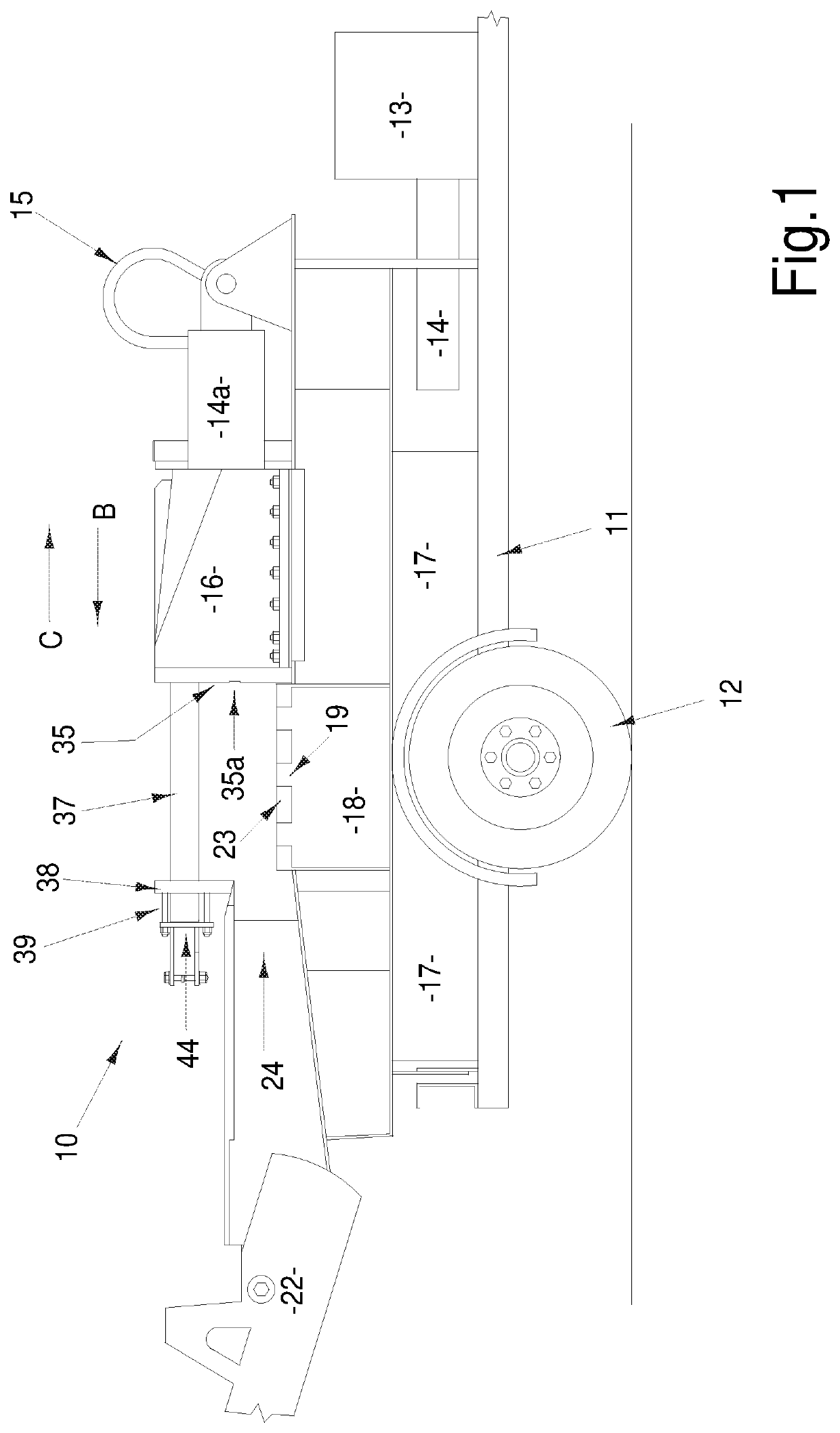
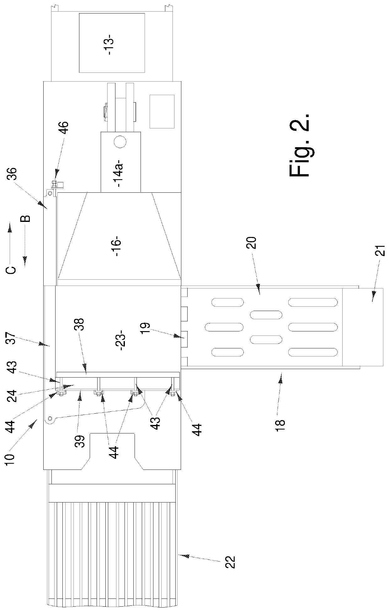
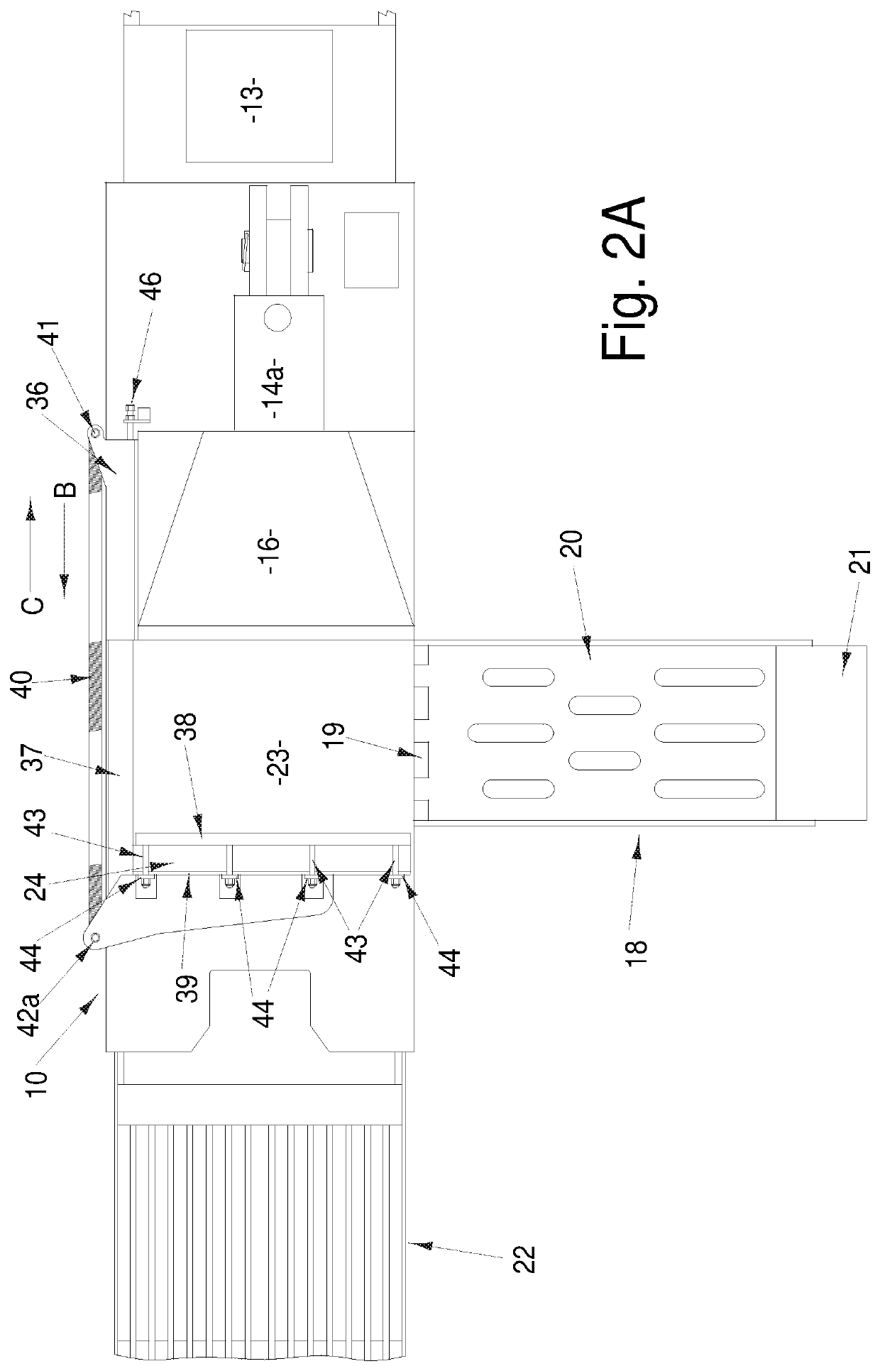
[0033]Referring to the drawings, a wood splitter 10 in accordance with the present invention includes a heavy duty trailer chassis 11 mounted on a pair of spaced wheels 12 and provided with a tow hitch (not visible) at the front of the chassis. It also would be possible to mount the splitter on a stationary chassis which can be positioned e.g. by a forklift.

[0034]A petrol or diesel powered motor 13 is mounted on the forward part of the chassis and powers a hydraulic pump 14. The hydraulic pump 14 is supplied with hydraulic fluid from a tank 17 mounted underneath the chassis, between the trailer wheels. Mounting the tank low down on the chassis ensures that the overall weight of the machine is kept as low as possible and the position also helps to protect the tank from accidental damage. However, the tank could be repositioned if necessary, or even positioned separate from the splitter.

[0035]The hydraulic pump 14 is connected to an hydraulic ram 14a which operates a moving head 16, t...


PUM


Abstract

A wood splitter which includes a supporting surface for receiving a section of wood to be split; the supporting surface having a cutting box on one side and a reciprocating moving head on the other side; the cutting box providing a series of spaced stationary knives through which the wood can be forced, to cut the wood, said stationary knives including a horizontal knife along the uppermost margin of the cutting box; the moving head being arranged to be reciprocable towards the cutting box so as to engage wood placed on the supporting surface and push said wood through the cutting box, and then away from the cutting box to allow a fresh piece of wood to be placed on the supporting surface; a top plate connected to the moving head by a connecting arm and movable between a first position in which the lower edge of the top plate overhangs said horizontal knife and a second position in which the top plate is raised vertically relative to the cutting box and is moved horizontally away from the supporting surface.

Description

TECHNICAL FIELD[0001]The present invention relates to a machine for splitting wood for firewood i.e receiving rounds of firewood and splitting those rounds into smaller pieces, of a size which can conveniently be placed into a log burner.BACKGROUND ART[0002]There are numerous different designs of log splitters in the marketplace. A majority of the splitters sold for private use or small-scale commercial use are relatively inexpensive machines which require rounds cut from logs to be manually positioned on a supporting surface and then a wedge-shaped cutter is forced into the round, to split the round in two; the cutter may move horizontally or vertically.[0003]A large round may require an initial cut to cut it into two, and then further cuts to cut the two sections down to acceptable firewood sizes. This is relatively slow, and for large rounds of firewood, the work of lifting the round up onto the supporting surface and then handling the sections as they are cut, is heavy work.[000...

Claims


Application Information

Patent Timeline
Patent Type & Authority Applications(United States)
IPC IPC(8): B27L7/06
CPCB27L7/06
Inventor SMITH, CHRISTOPHER ALANOLDHAM, WESLEY DAVIDCUNNINGHAM, EDWARD PHILLIP
Owner TASKPOWER NZ LTD
Why Eureka
Try Eureka