Vehicular sun visor

a sun visor and sunglass technology, applied in the field of sun glasses, can solve the problems of small dynamic friction coefficient of the clip, slow down, and small hammering sound to be caused when the visor body hits the ceiling, and achieve the effect of reducing the hammering sound to the ceiling caused when the visor body is stored

Pending Publication Date: 2022-09-08
KYOWA SANGYO
View PDF2 Cites 0 Cited by
  • Summary
  • Abstract
  • Description
  • Claims
  • Application Information

AI Technical Summary

Benefits of technology

[0007]In view of this, conventionally, there has been required a sun visor which has contradictory functions of a function to smoothly rotate a visor body at a usage position and a function to reduce the rotating speed of the visor body at the time of bringing the visor body close to a ceiling by use of a leaf spring so as to reduce a hammering sound to be caused when the visor body hits the ceiling and which surely enables the visor body to reach the ceiling at the time when the visor body is brought into contact with the ceiling by use of the leaf spring.
[0009]Accordingly, a sliding resistance between the support shaft and the clip can be reduced by the surface treatment performed on the abutment region. Besides, the rotation speed at the time when the visor body rotates to the storage position after the visor body approaches a ceiling or the like can be reduced. This is because, as a result of diligent study of the inventors, it is found that a dynamic friction coefficient between the outer peripheral surface of the support shaft and the clip subjected to the surface treatment depends on the speed. That is, the clip moves to the ceiling together with the visor body by increasing its speed by use of the planar region of the support shaft. Meanwhile, the dynamic friction coefficient between the support shaft and the clip becomes larger as the speed becomes faster. As a result, the speed at the time when the visor body approaches the ceiling slows down, so that a hammering sound to be caused when the visor body hits the ceiling becomes small. On the other hand, when the speed of the visor body slows down, the dynamic friction coefficient of the clip becomes small. Thus, the sun visor has contradictory functions of a function to smoothly rotate the visor body and a function to reduce the speed at the time of storing the visor body, and the visor body can be surely stored in the ceiling.
[0010]According to another feature of this disclosure, the surface treatment is performed by coating the abutment region with a coating material having a characteristic that a dynamic friction coefficient increases as a sliding rotation speed of the clip relative to the support shaft becomes faster. Generally, at the time when the visor body moves toward the ceiling by use of an elastic force from the clip, the rotation speed of the visor body tends to become fast just before the visor body hits the ceiling. This tendency is relaxed when the dynamic friction coefficient of the clip relative to the support shaft increases. This consequently prevents the visor body from hitting the ceiling or the like at a speed faster than required. Thus, a hammering sound of the visor body to the ceiling that can be caused when the visor body is stored can be reduced.
[0012]Accordingly, by performing the surface treatment, the sliding resisting force between the support shaft and the clip becomes larger as the sliding rotation of the visor body becomes faster, in comparison with a case where grease is applied between the support shaft and the clip as general in a conventional vehicular sun visor. Thus, a hammering sound to the ceiling that can be caused when the visor body is stored can be reduced.

Problems solved by technology

As a result, the speed at the time when the visor body approaches the ceiling slows down, so that a hammering sound to be caused when the visor body hits the ceiling becomes small.
On the other hand, when the speed of the visor body slows down, the dynamic friction coefficient of the clip becomes small.

Method used


Image

  • Vehicular sun visor
  • Vehicular sun visor
  • Vehicular sun visor

Examples


Embodiment Construction

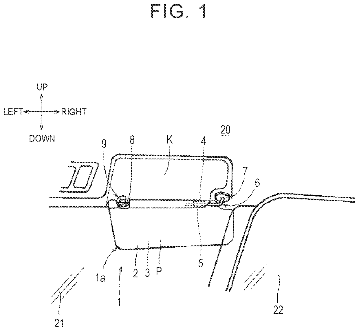
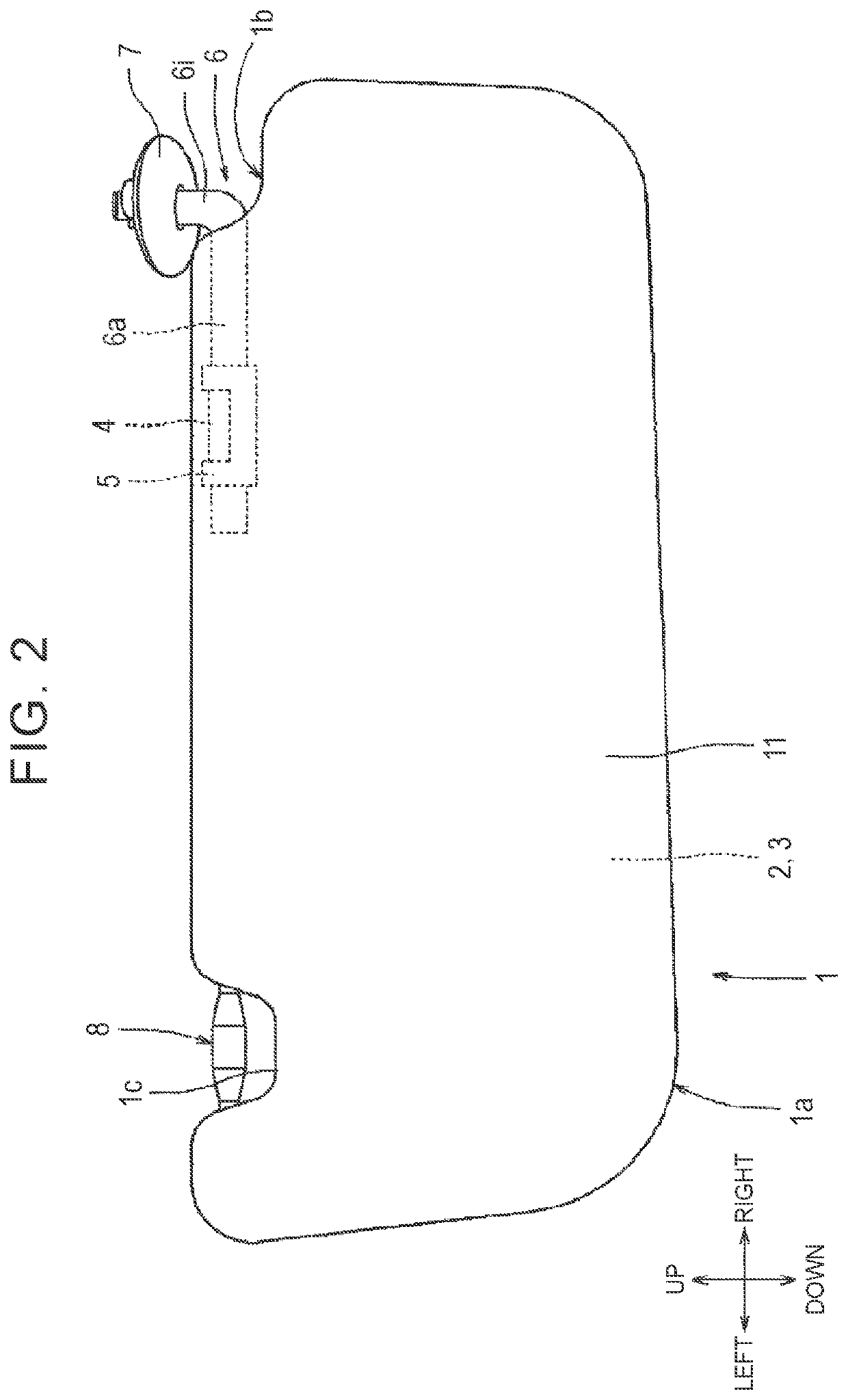
[0031]One embodiment of the present invention will be described with reference to FIGS. 1 to 3. As illustrated in FIG. 1, a vehicular sun visor 1 is attached to a ceiling surface 20 near a windshield 21. The vehicular sun visor 1 includes a visor body 1a constituted by a first component 2 and a second component 3 each having a generally plate shape. The surface of the visor body 1a is covered with a skin 11. A shaft 8 is attached to a hook 9, so that the visor body 1a rotates around the shaft 8 and a horizontal shaft 6a between a usage position P along the windshield 21 and a storage position K along the ceiling surface 20.

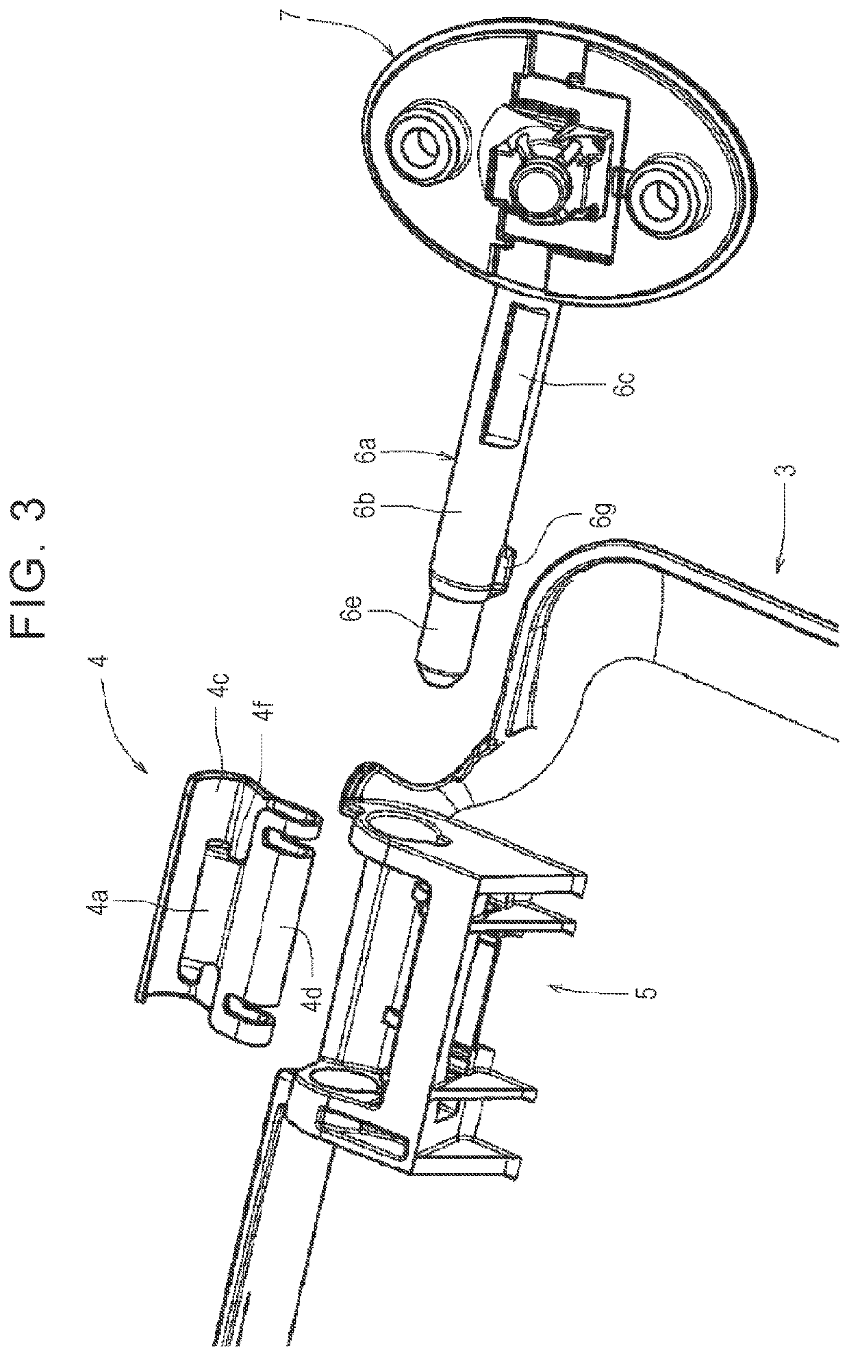
[0032]As illustrated in FIGS. 2, 3, the support shaft 6 is a generally L-shaped bar and includes the horizontal shaft 6a and a vertical shaft 6i. The horizontal shaft 6a includes a large-diameter portion 6b and a small-diameter portion 6e on the same axis. A generally rectangular slot surface 6c is formed on the outer peripheral surface of the large-diameter porti...


PUM


Abstract

A vehicular sun visor has a plate-shaped visor body, and a support shaft inserted into the visor body. The visor body is provided with a clip into which the support shaft is inserted. The outer peripheral surface of the support shaft includes a planar region that abuts the clip when the visor body is positioned in a storage position. The clip has a clip body made of elastically deformable metal, and has a pressing part that slidably abuts the outer peripheral surface of the support shaft including the planar region. The pressing part of the support shaft is applied with a surface treatment.

Description

TECHNICAL FIELD[0001]The present invention relates to a sun visor provided in a vehicle. For example, the present invention relates to a sun visor including a plate-shape visor body and used such that the visor body rotates between a usage position along a windshield of a vehicle and a storage position along a ceiling.BACKGROUND ART[0002]A vehicular sun visor described in Patent Document 1 includes a plate-shaped visor body, and a support shaft inserted into the visor body and supporting the visor body rotatably. The support shaft has a generally columnar shape. A gripper configured to grip the support shaft rotatably is provided inside the visor body. At the time when the visor body is rotated around the support shaft between a usage position along a windshield and a storage position along a ceiling, the gripper rotates together with the visor body while the gripper slides relative to the support shaft.[0003]Generally, the rotation operation of the visor body is performed by hand. ...

Claims


Application Information

Patent Timeline
Patent Type & Authority Applications(United States)
IPC IPC(8): B60J3/02
CPCB60J3/0278B60J3/0265B60J3/0252
Inventor MATSUKI, NOBUAKI
Owner KYOWA SANGYO
Why Eureka
Try Eureka