Sinker Assembly Using Elastic Body
a sinker assembly and elastic technology, applied in the field of sinker assembly using elastic body, can solve the problem that the weight of the sinker assembly cannot be changed quickly
- Summary
- Abstract
- Description
- Claims
- Application Information
AI Technical Summary
Benefits of technology
Problems solved by technology
Method used
Image
Examples
first embodiment
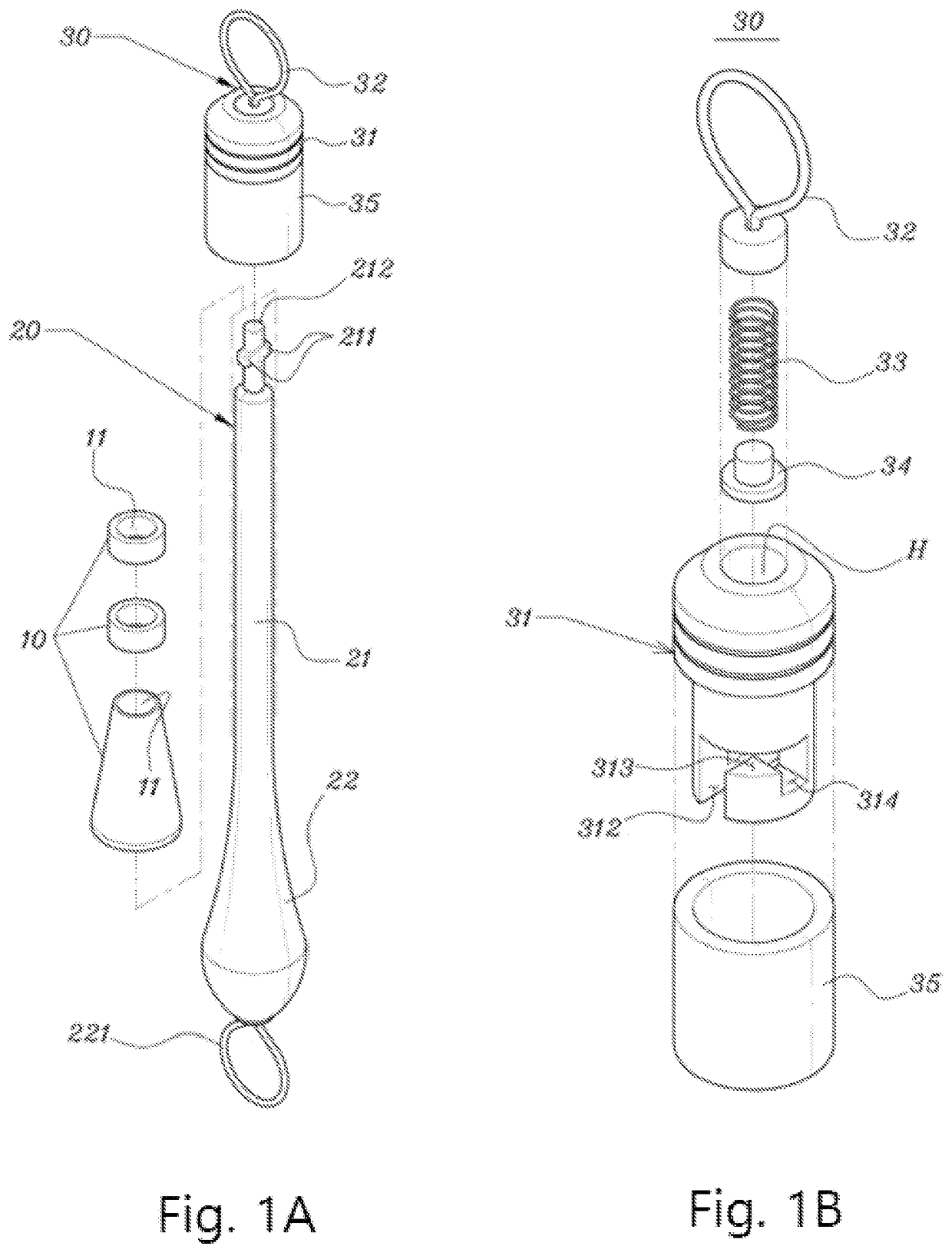
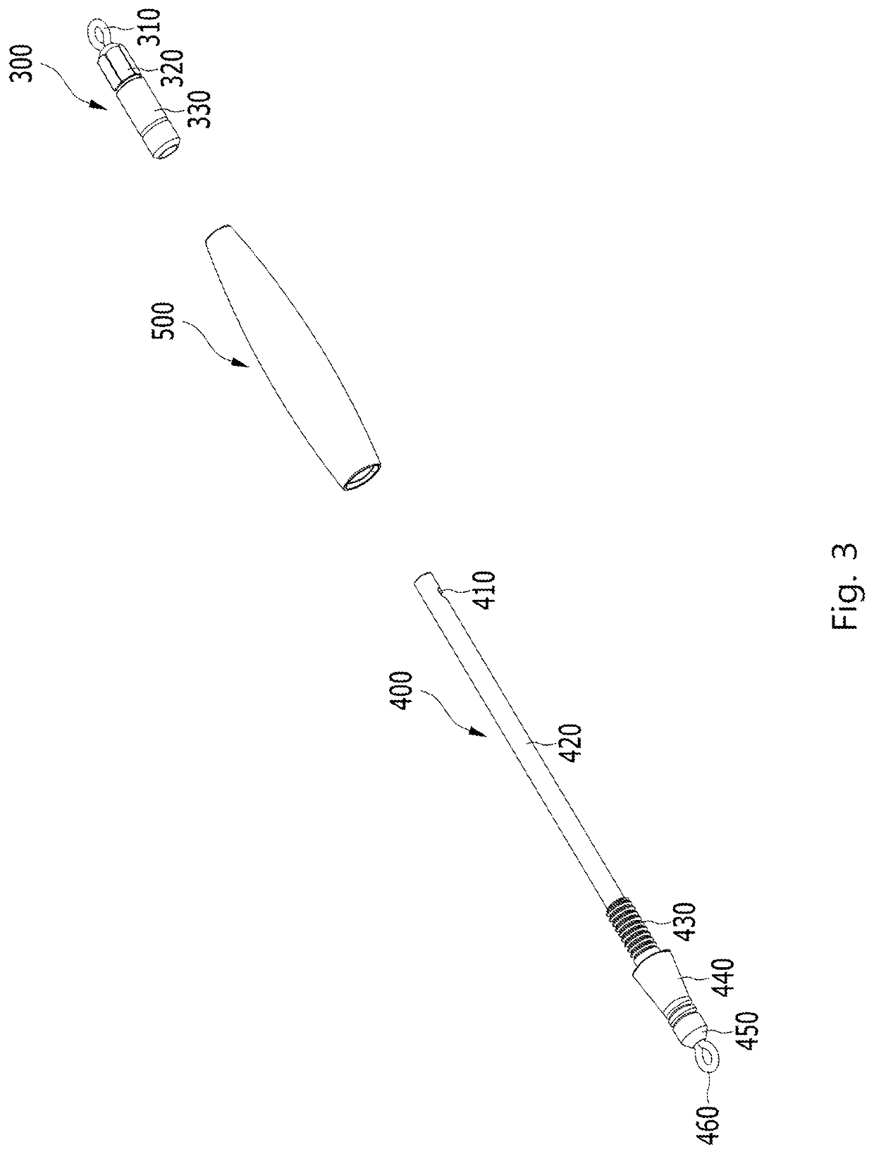
[0117]Referring back to FIG. 3 to explain a representative embodiment of the present disclosure, the first member 600 may be the cap section 300, and the second member 700 may be the holder section 400. The cap section 300 including the receptacle part 330 may be connected to the holder section 400 including the fastening part 410.
[0118]FIGS. 9A and 9B are exploded views illustrating a sinker assembly using an elastic body 331 composed of a first member 600 to a third member 800 according to an embodiment of the present disclosure. In this embodiment, the third member 800 may be connected to the second member 700.
[0119]The third member 800 may include a cap section 300, a holder section 400, a pole line or a float fishing fitting, as one component constituting the fishing fittings. In order for the third member 800 to be connected to the second member 700, the second member 700 may include a second receptacle part 710 having the same structure as the receptacle part 330 of the firs...
second embodiment
[0121]Referring to FIGS. 9A and 9B, the third member 800 may include a second fastening part 820 at one end and a ring at the other end. In this case, the third member 800 may serve as a lower cap section corresponding to the cap section 300. A ring may be connected to a fishing line, a pole line, and the like.
[0122]In addition, the third member 800 may further include a weight part 830. The weight part 830 may serve as a gripping portion in the process of connecting the third member 800 to the second member 700. The weight part 830 may have various weights to provide additional weight to the sinker 500.
third embodiment
[0123]Referring back to FIG. 8, the first member 600 may include the cap section 300, the second member 700 may include the holder section 400, the third member 800 may include a first post line 850, and the fourth member 900 may include a second post line 950. The fourth member 900 may be connected to the third member 800, the fifth member 1000 may be connected to the fourth member 900, and the fifth member 1000 may include a float fishing sinker. The float fishing sinker may have various weights to provide weight, and may connect various types of float fishing fittings.
[0124]Although the third embodiment illustrates the connection structure of the first member 600 to the fifth member 1000, the present disclosure is not necessarily limited to this structure. In the present disclosure, respective members can be modified in diverse forms, and the present disclosure can be implemented by connecting additional components of the sixth member or more.
[0125]In addition, as illustrated in...
PUM
 Abstract
Description
Claims
Application Information
 - R&D
- Intellectual Property
- Life Sciences
- Materials
- Tech Scout
- Unparalleled Data Quality
- Higher Quality Content
- 60% Fewer Hallucinations
Browse by: Latest US Patents, China's latest patents, Technical Efficacy Thesaurus, Application Domain, Technology Topic, Popular Technical Reports.
© 2025 PatSnap. All rights reserved.Legal|Privacy policy|Modern Slavery Act Transparency Statement|Sitemap|About US| Contact US: help@patsnap.com


