Keyswitch assembly and support mechanism thereof
- Summary
- Abstract
- Description
- Claims
- Application Information
AI Technical Summary
Benefits of technology
Problems solved by technology
Method used
Image
Examples
first embodiment
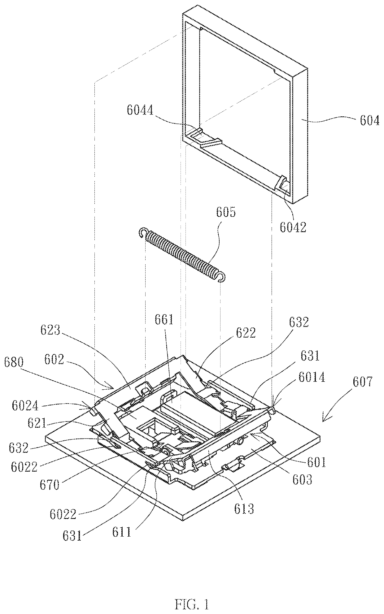
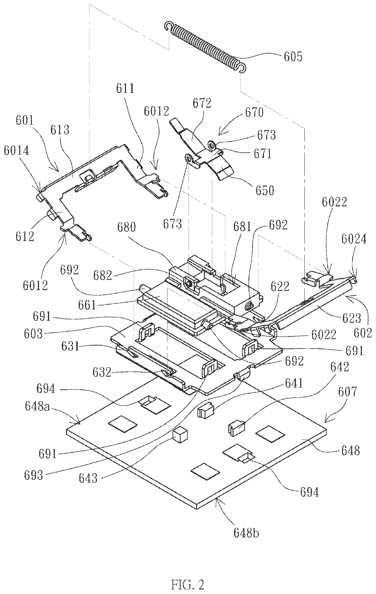
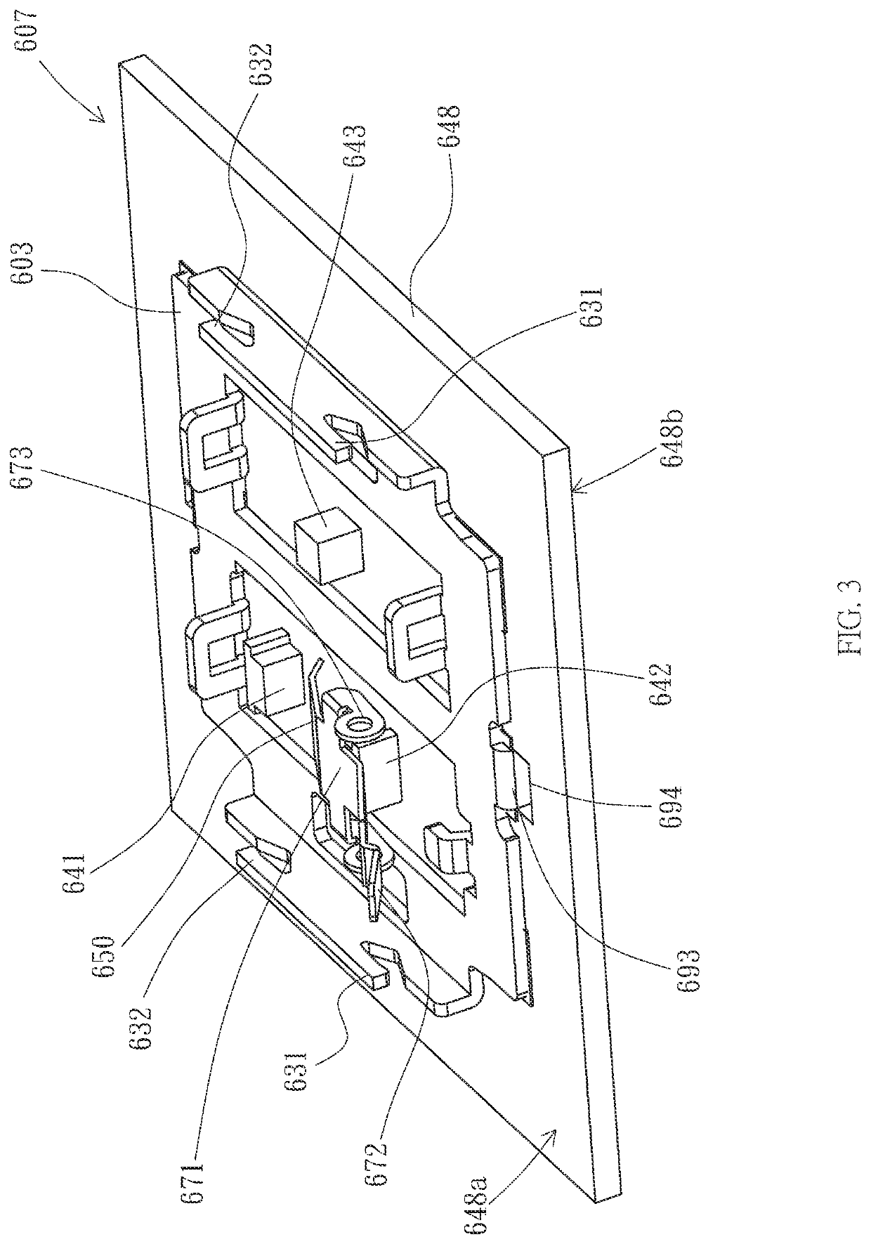
[0032]Referring again to FIG. 3 and FIG. 4, in a first embodiment, the sensing signal S is light of specific wavelength, especially infrared light. The light emitter 641 projects light of specific wavelength as the sensing signal to the light receiver 642, and the light receiver 642 receives the light of specific wavelength to corresponding obtain the sensing intensity. In general, the light receiver 642 receives the light to generate a corresponding voltage signal, so the sensing intensity can be the voltage value of the voltage signal generated by the light receiver 642 after receiving the light of specific wavelength.
[0033]In a different embodiment, the signal generator and the signal sensor can be a magnet and a Hall sensor, respectively. The magnet is configured to create a magnetic field as the sensing signal, and the Hall sensor is configured to sense the exist and magnitude of the magnetic field through Hall effect, so as to obtain the sensing intensity. The output voltage o...
second embodiment
[0072]Referring to FIG. 14 and FIG. 15, in a second embodiment, the invention discloses a keyswitch assembly, which is provided for explaining a variant embodiment of the blocking mechanism.
[0073]As shown in FIG. 14 and FIG. 15, the blocking mechanism 670 includes a pivoting portion 671, a connecting piece 672, and a blocking piece 650. The pivoting portion 671 is rotatably disposed on the top surface 648a of the substrate 648. The rotation axis of the pivoting portion 671, the rotation axis of the first frame 601, and the rotation axis of the second frame are substantially parallel.
[0074]As shown in FIG. 14 and FIG. 15, the connecting piece 672 extends from the pivoting portion 671, and in the second embodiment, the connecting piece 672 is a longitudinal strip disposed vertical to the top surface 648a. The distal end of the connecting piece 672 has a notch 672a. The opening of the notch 672a is located at the distal end of the connecting piece 672. The notch 672a extends toward the...
third embodiment
[0081]Referring to FIG. 18 and FIG. 19, in a third embodiment, the invention discloses a keyswitch assembly, which is provided for explaining a variant embodiment of the linkage mechanism.
[0082]As shown in FIG. 18 and FIG. 19, the pressing piece 711 and the receiving piece 712 in the second embodiment are generally slightly bent downward (e.g. bent toward the substrate 648). Moreover, the front end of the receiving piece 712 is provided with a receiving portion 712a, which is bent upward (e.g. bent away from the substrate 648), and a bending angle exists between the receiving portion 712a and the receiving piece 712. Referring again to FIG. 19, the bending angle of the receiving piece 712 is larger than the bending angle of the pressing piece 711, and the length of the pressing piece 711 is larger than the length of the receiving piece 712. Similar to the first embodiment, the two side arms 611 and 612 of the first frame 601 and the two side arms 621 and 622 of the second frame 602 ...
PUM
 Abstract
Description
Claims
Application Information
 - R&D
- Intellectual Property
- Life Sciences
- Materials
- Tech Scout
- Unparalleled Data Quality
- Higher Quality Content
- 60% Fewer Hallucinations
Browse by: Latest US Patents, China's latest patents, Technical Efficacy Thesaurus, Application Domain, Technology Topic, Popular Technical Reports.
© 2025 PatSnap. All rights reserved.Legal|Privacy policy|Modern Slavery Act Transparency Statement|Sitemap|About US| Contact US: help@patsnap.com


