Image forming apparatus

a technology of image forming and forming tubes, which is applied in the direction of electrographic process apparatus, instruments, corona discharge, etc., can solve the problems of unnecessary consumption of toner, contamination of images and recording materials, and a tendency to become relatively complicated control, etc., to achieve the effect of suppressing toner movement and shortening fpo

Pending Publication Date: 2022-11-03
CANON KK
View PDF8 Cites 0 Cited by
  • Summary
  • Abstract
  • Description
  • Claims
  • Application Information

AI Technical Summary

Benefits of technology

[0008]A principal object of the present invention is to provide an image forming apparatus capable of shortening FPOT while suppressing movement of toner to a region on a photosensitive member exposed to light during actuation of an exposure device.

Problems solved by technology

For that reason, in the case where the developing member is contacted to the photosensitive member when a region on the photosensitive member exposed to light by the forced light emission passes through a developing position where the photosensitive member and the developing member are in contact with each other, toner is moved from the developing member to the above-described region on the photosensitive member, so that the toner is unnecessarily consumed.
Further, there is a possibility that this toner causes contamination of an image and a recording material with the toner during subsequent image formation.
However, in this method, there is a need to always apply and control a charging voltage and a developing voltage during the actuation of the exposure device, so that there is a possibility that control is liable to become relatively complicated and that this method is disadvantageous in terms of life times of the photosensitive member and the developing unit.

Method used


Image

  • Image forming apparatus
  • Image forming apparatus
  • Image forming apparatus

Examples


embodiment 1

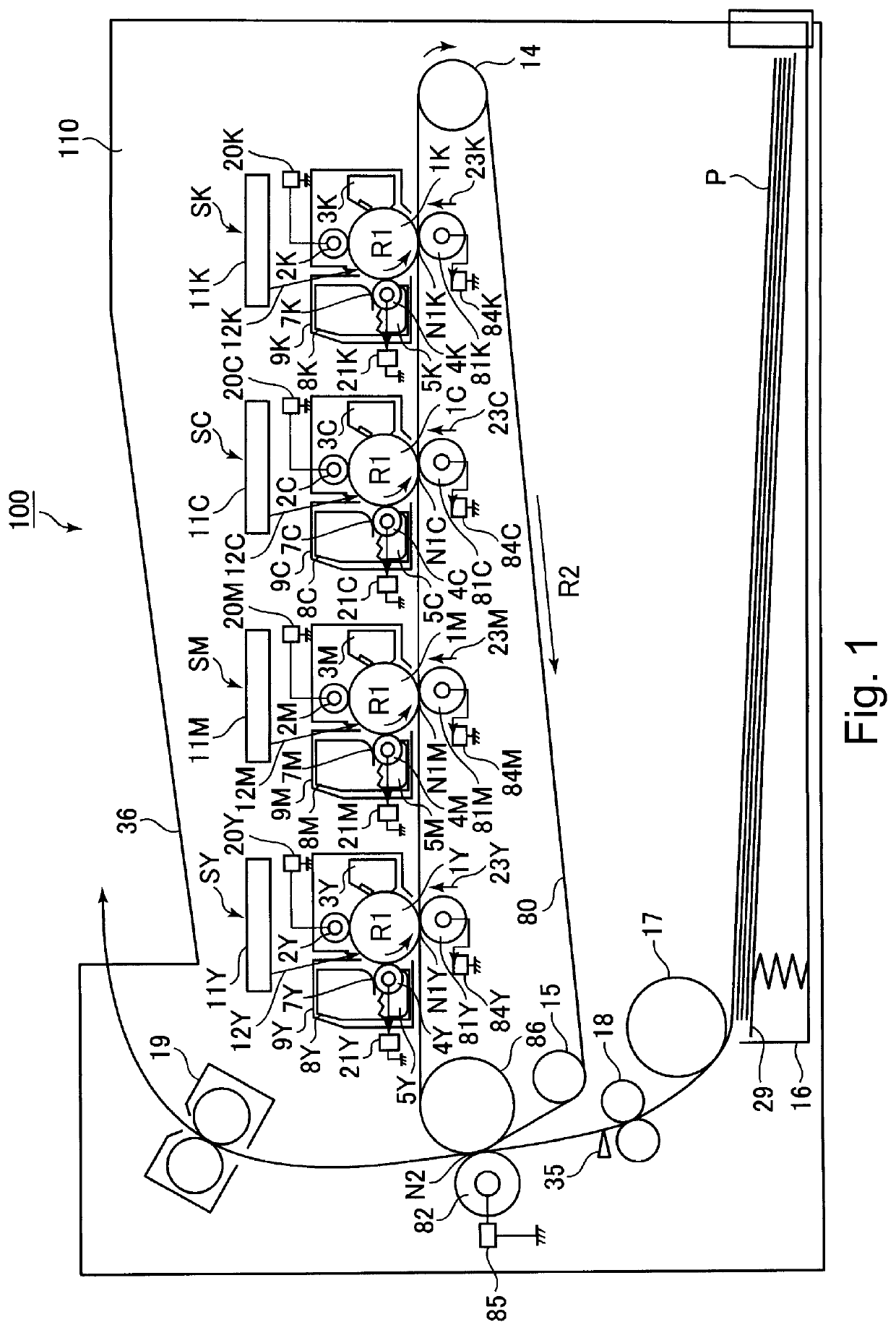
[0030]FIG. 1 is a schematic sectional view of the image forming apparatus 100 of the The image forming apparatus 100 of this embodiment is a printer (color image forming apparatus) of a tandem type in which a full-color image is capable of being formed by using an electrophotographic type and in which an intermediary transfer type is employed.

[0031]The image forming apparatus 100 includes, as a plurality of image forming portions (stations), first to fourth image forming portions SY, SM, SC and SK for forming images with toners of colors of yellow (Y), magenta (M), cyan (C) and black (K), respectively. These four image forming portions SA, SM, SC and SD are disposed in line with substantially certain intervals along a movement direction of an intermediary transfer belt 13 on an image transfer side described later. In the embodiment 1, with respect to a movement direction of the intermediary transfer belt 80, the image forming portions for the respective colors are successively disp...

embodiment 2

[0145]In the embodiment 2, depending on input of a commercial power source used by the image forming apparatus 100, fluctuation in time required for the rising of the developing motor 101 is predicted, and the contact operation start timing of the developing roller 4 is changed.

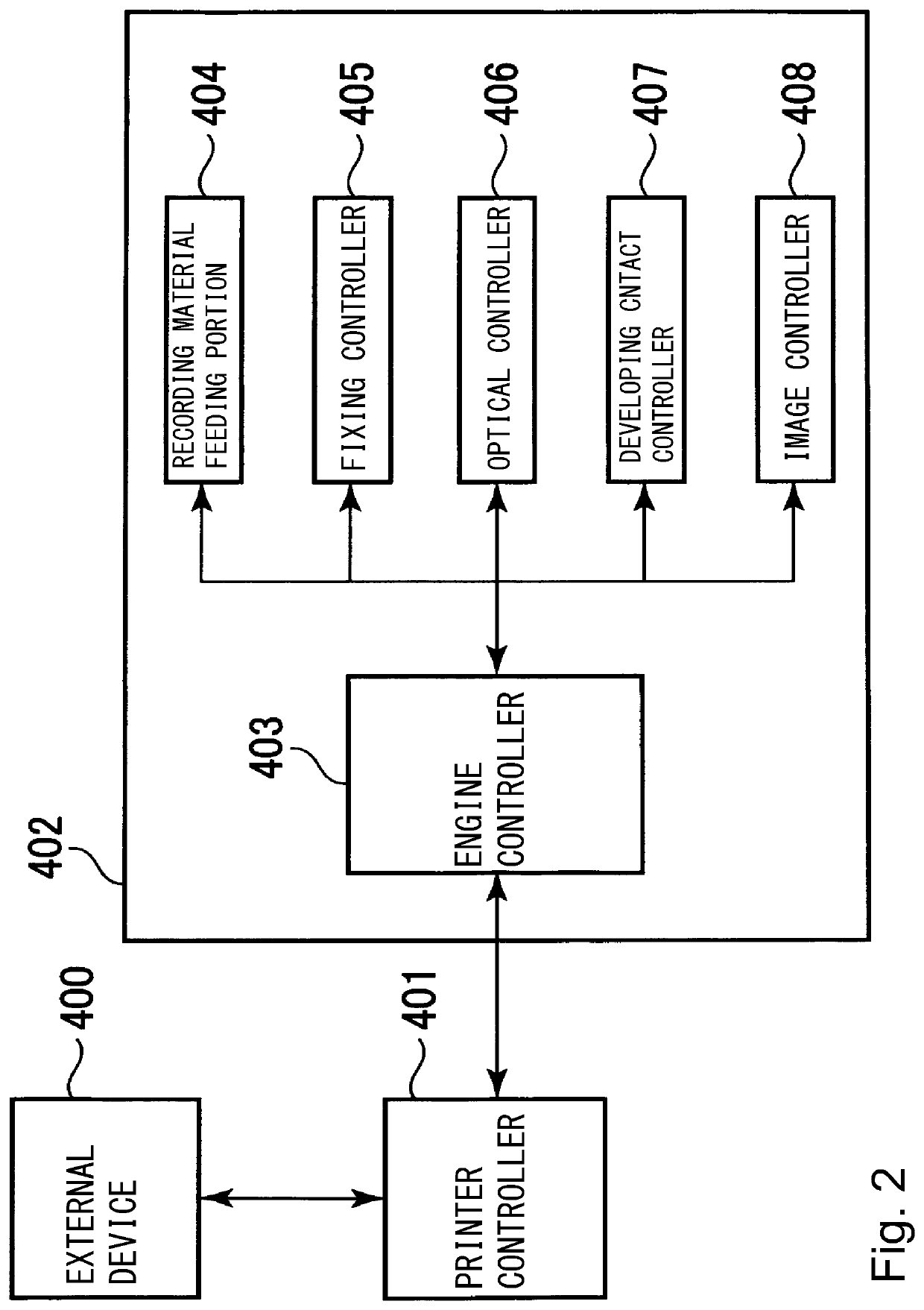
[0146]FIG. 16 is a function block diagram for illustrating a system constitution of the image forming apparatus 100 of the embodiment 2. The system constitution of the image forming apparatus 100 of this embodiment is roughly similar to the system constitution of the image forming apparatus 100 of the embodiment 1 described using FIG. 2. However, in the embodiment 2, the printer engine 402 is provided with a power source controller 409. On the basis of an instruction from the engine controller 403, the power source controller 409 controls supply of electric power necessary to be outputted from the respective controllers (the recording material feeding portion 404, the fixing controller 405, the optical contro...


PUM


Abstract

An image forming apparatus includes a photosensitive member, a charging member, an exposure unit, a developing unit including a developing member, a motor, a contact and separation unit, a controller, an acquiring portion for acquiring information on a switching time which is a time required for switching a state of the developing member from a separated state to a contact state by executing a contact operation by the contact and separation unit, and a setting portion for setting, on the basis of the information on the switching time acquired by the acquiring portion, a start timing which is a timing when the contact operation by the contact and separation unit is started in a preparation operation and which is a timing before a region on the photosensitive member exposed to light in a light emission period reaches a developing position.

Description

FIELD OF THE INVENTION AND RELATED ART[0001]The present invention relates to an image forming apparatus, such as a printer, a copying machine, or a facsimile machine, using an electrophotographic type.[0002]In the image forming apparatus such as a laser beam printer using the electrophotographic type, lifetime extension of various (component) parts is realized for improving an image quality and for reducing a running cost. For example, in a constitution employing a contact development type such that an electrostatic latent image on a photosensitive member is developed by bringing a developing member such as a developing roller into contact with the photosensitive member, the developing member is separated (spaced) from the photosensitive member in advance during stand-by or the like and is contacted to the photosensitive member during image formation. By employing such a constitution, deterioration of the photosensitive member and the developing member is suppressed, so that the lif...

Claims


Application Information

Patent Timeline
Patent Type & Authority Applications(United States)
IPC IPC(8): G03G15/02G03G15/043G03G15/00G03G15/08
CPCG03G15/0266G03G15/043G03G15/5008G03G15/5037G03G15/0813G03G21/1825
Inventor ENDO, HIROTO
Owner CANON KK
Why Eureka
Try Eureka