
Corrective appliance

a technology of corrective appliance and rod member, which is applied in the direction of internal osteosynthesis, internal osteosynthesis, osteosynthesis devices, etc., can solve the problem of difficult engagement of rod member with the top-opening groove of the screw member

Pending Publication Date: 2022-11-10
MIZUHO IKA KOGYO KK
View PDF0 Cites 1 Cited by
  • Summary
  • Abstract
  • Description
  • Claims
  • Application Information

AI Technical Summary

Benefits of technology

The corrective appliance described in this patent can help to correct spinal deformities without causing any damage to the rods used in the process. Its technical effect is to provide better support and protection for the spinal column during surgical correction and fusion.

Problems solved by technology

At this time, the rod member extends linearly while the spine is deformed to make it quite difficult to engage the rod member with the top-opened groove of the screw member and that of hook member.

Method used


Image

  • Corrective appliance
  • Corrective appliance
  • Corrective appliance

Examples


first embodiment

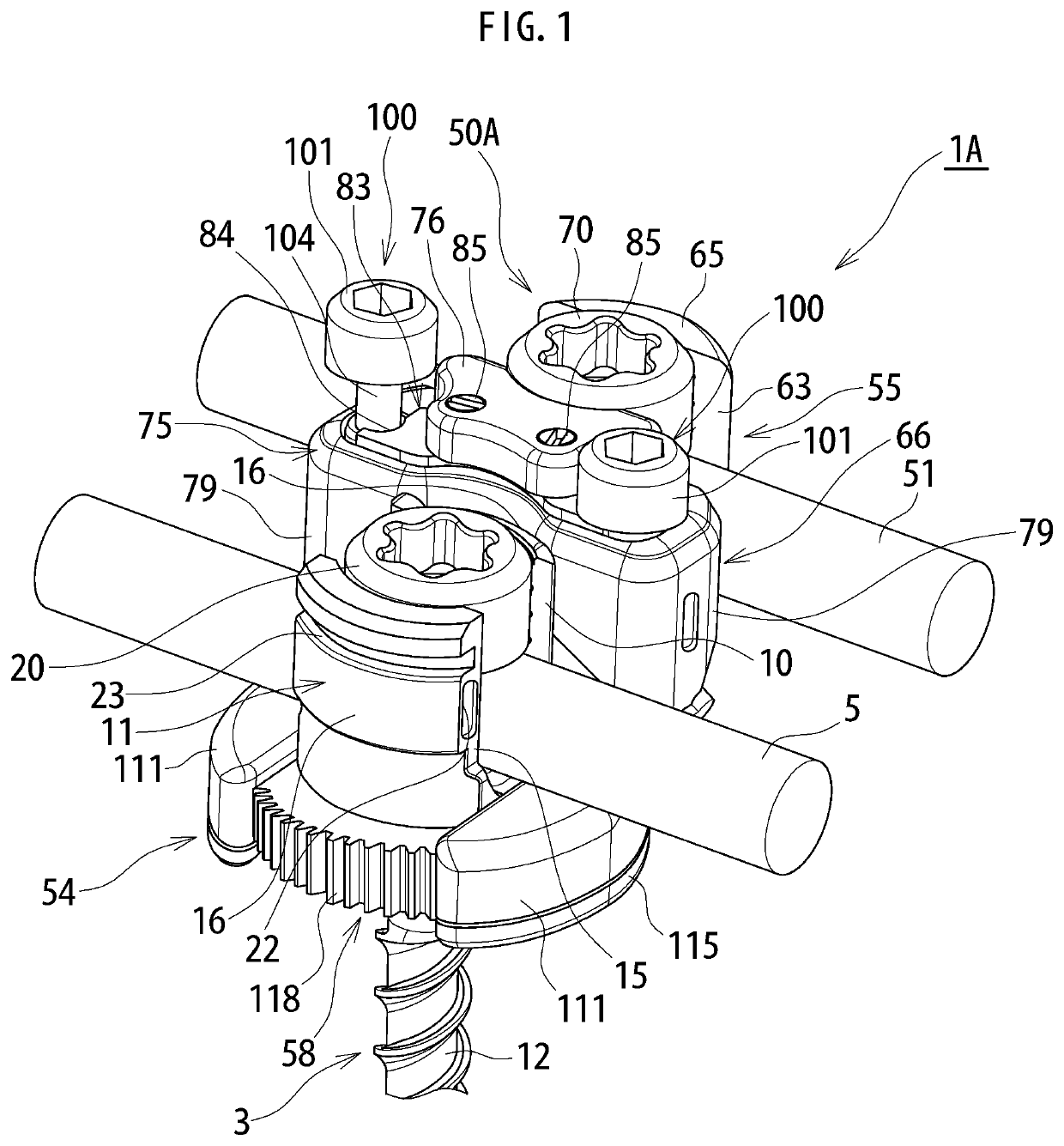
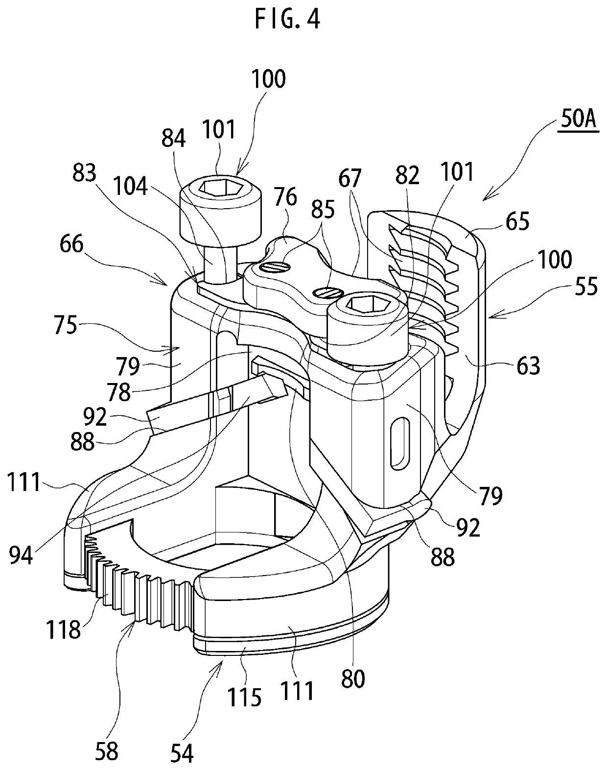
[0048]A corrective appliance 1A according to the present invention will be described first in detail on the basis of FIGS. 1 to 8.

[0049]The corrective appliance 1A according to the first embodiment of the present invention is to assist in correction and fusion when spinal deformity is subjected to the correction and fusion by a spinal deformity correction and fusion system 2 (see FIG. 8(f)). The spinal deformity correction and fusion system 2 briefly includes: a plurality of screw members 3 (see FIGS. 1 and 2) each to be screwed into a vertebral body through a pedicle of each vertebra of a spine; a plurality of hook members 4 (see FIG. 3) each to be hooked on a pedicle, a vertebral arch, or a transverse process, for example, of each vertebra; and a rod member 5 (see FIG. 1) to be coupled to a groove 10 of each screw member 3 and to a groove 24 of each hook member 4 and extending along an axis direction of a spine. These screw members 3 and hook members 4 correspond to a vertebra fix...

second embodiment

[0100]The male threads 190 of the operative screw member 153 are arranged in the housing hollow section 165 of the main body unit 150 while being threadedly engaged with the female threads at the cylindrical section 181 of the wedge slide member 152. The head 189 of the operative screw member 153 is housed in the housing cavity 164 of the main body unit 150 (main body unit section 161), and the upper surface of the head 189 and the upper surface of the main body unit 150 (main body unit section 161) except the housing cavity 164 are arranged on substantially the same plane. Furthermore, the regulating plate member 154 is arranged in such a manner as to cover the upper surface of the main body unit section 161 of the main body unit 150 and the head 189 of the operative screw member 153, and is fixed with the attachment bolt 193 to the main body unit 150. In this way, the clamp member 50B used in the corrective appliance 1B is completed.

[0101]For attachment of the clamp member 50B of...


PUM


Abstract

To provide a corrective appliance capable of properly assisting in correction of spinal deformity by a spinal deformity correction and fusion system while limiting damage on a rod member when the spinal deformity is subjected to correction and fusion by the spinal deformity correction and fusion system. A corrective appliance includes: a clamp member to be attached detachably to a screw member, for example, and to be arranged close to the screw member; and an auxiliary rod member to be attached detachably to the clamp member and to be used for correcting spinal deformity. This allows the corrective appliance to properly assist in correction of spinal deformity by a spinal deformity correction and fusion system while limiting damage on a rod member when the spinal deformity is subjected to correction and fusion by the spinal deformity correction and fusion system.

Description

TECHNICAL FIELD[0001]The present invention relates to a corrective appliance for assisting in correction and fusion during implementation of spinal deformity correction and fusion surgery in which spinal deformity is subjected to the correction and fusion by a spinal deformity correction and fusion system including a vertebra fixing tool to be fixed to each of a plurality of vertebrae and a rod member to be coupled to the vertebra fixing tool.BACKGROUND ART[0002]In a normal condition of a spine, the spine is generally straight when viewed from the back, cervical vertebrae and lumbar vertebrae curve forward and thoracic vertebrae and sacral vertebrae curve backward when viewed from the side. In this way, the spine shows an approximately S-shaped appearance. Spinal deformity causing abnormality at the spine is a disease with the deformed spine, and includes scoliosis, kyphosis, and kyphoscoliosis, for example. Scoliosis is a disease in which the spine is twisted while being curved lat...

Claims


Application Information

Patent Timeline
Patent Type & Authority Applications(United States)
IPC IPC(8): A61B17/70
CPCA61B17/705A61B17/7056A61B17/7002A61B17/7049A61B17/7032
Inventor EBARA, SOHEI
Owner MIZUHO IKA KOGYO KK
Learn More