Device for correcting spinal deformities

a technology for spinal deformation and devices, applied in the field of devices for and a method of correcting spinal deformation, can solve the problems of limited control of sagittal plane correction of the harrington system, loss of lumbar lordosis, and inability to achieve postoperative external support,

Active Publication Date: 2011-07-12
HONG KONG UNIV OF +1
View PDF14 Cites 15 Cited by
  • Summary
  • Abstract
  • Description
  • Claims
  • Application Information

AI Technical Summary

Benefits of technology

[0014]The present invention relates generally to spinal deformity correction. More specifically, the present invention is capable of providing a constant or substantially constant correction force or a similar correction force and maintaining such correction force constant or substantially constant until spinal deformities are corrected. The present invention can correct various spinal deformities including scoliosis, kyphosis, lordosis, and the rotation around the longitudinal axis of the spine. Additionally or alternatively, the present invention can provide horizontal plane correction of spinal deformities.

Problems solved by technology

However, a loss of lumbar lordosis, or the “flatback” effect, can occur when using the Harrington system along with distraction over the lumbar spine.
Nevertheless, the Harrington system can have limited control of sagittal plane correction, limited derotation, and high rate of hook dislodgment in the lumbar spine, encounter distraction rod fracture, and require postoperative external support.
However, complications associated with iliac screw breakage, transverse connector breakage and screw breakage at the end of constructs have occurred when using the Isola system.
The various conventional correction systems however fail to provide complete correction of scoliotic spines.
Such correction systems can reduce spinal deformity by only 60% to 70%, but a full correction is almost impossible.
The use of excessive correction forces in attempting a full correction can cause bony fractures or neurological deficit due to spinal cord damage.
Moreover, none of the conventional correction systems takes into account the viscoelastic behavior of the spine.
This loss of tension within the correction systems can cause a partial recurrence of deformity subsequent to the correction.
Consequently, conventional correction systems can cause a loss of correction for up to 15% as a result of this effect.
Furthermore, because scoliosis correction is carried out instantaneously and only at the time of surgery with no time for the tissues to relax, the load on the spine rises rapidly.
The increased load on the corrected spine limits the amount of correction force that is safely possible.
Thus, viscoelastic behavior of spinal tissues can limit the amount of correction force and in turn the correction rate.
If excessive correction forces are used, they can cause bony fractures.
In addition, neurological deficit can occur due to rapid over-stretching of the spinal cord.
Conventional systems providing gradual or constant correction forces nevertheless require some form of repeated surgery or post-operative care, resulting in longer hospitalization as well as patient inconvenience and discomfort.
However, the mechanical strength of SME was insufficient to fully correct spinal deformities.

Method used


Image

  • Device for correcting spinal deformities
  • Device for correcting spinal deformities
  • Device for correcting spinal deformities

Examples


first embodiment

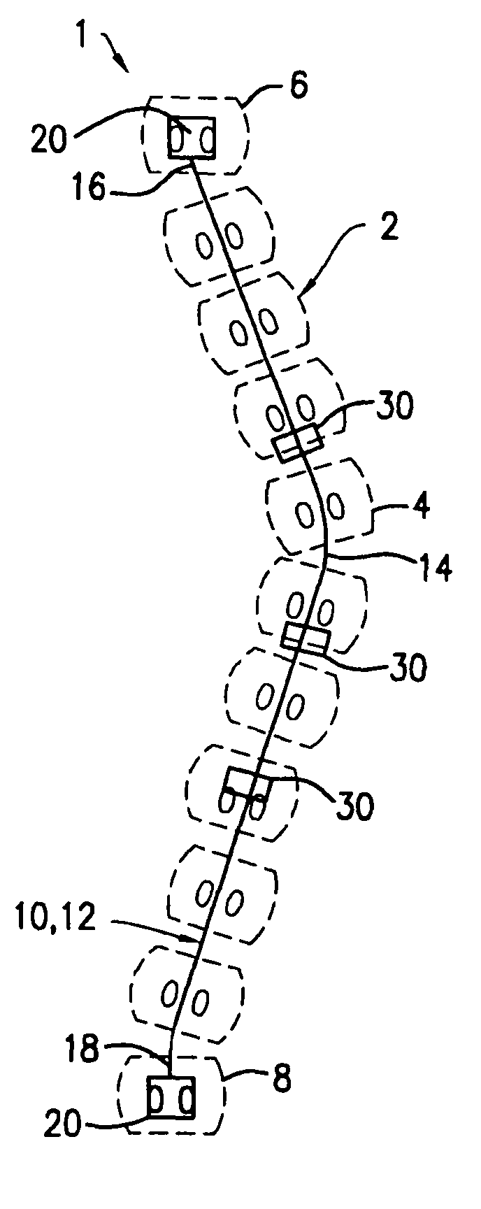
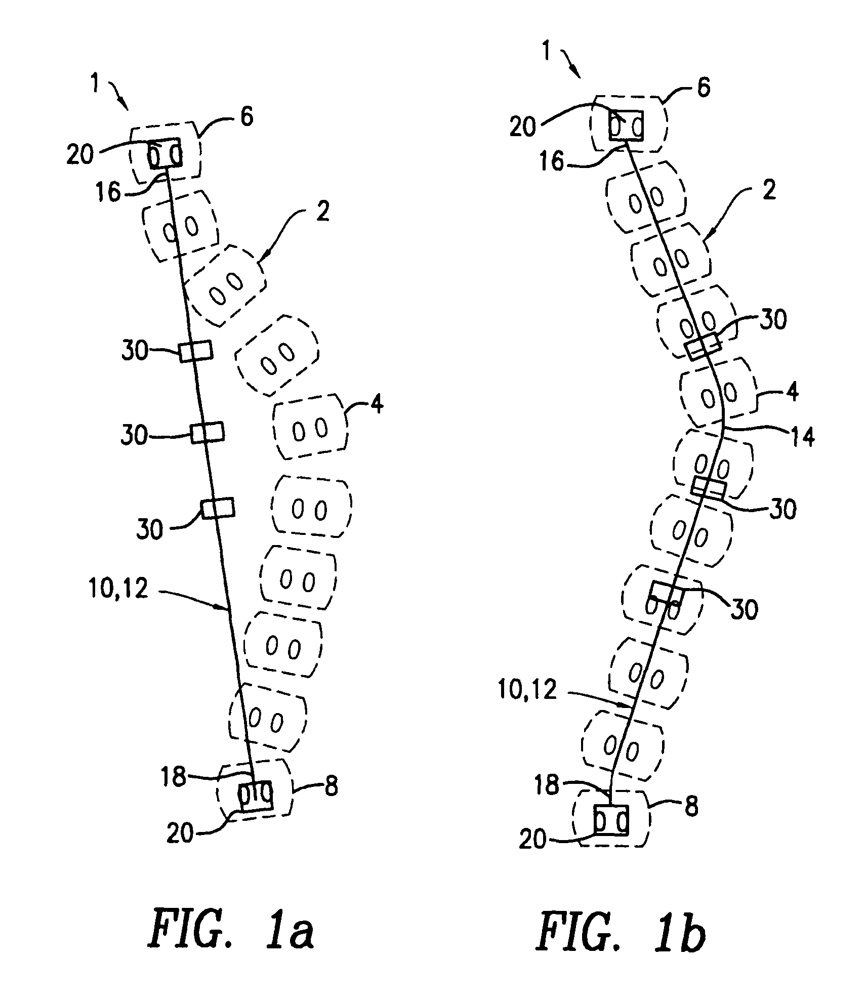
[0045]FIGS. 1a and 1b show the correction device 1 for correcting various spinal deformities, such as scoliosis. The correction device 1 can be in various forms and be mounted onto at least a portion of the spine 2. For example, the correction device 1 can be either applied to the vertebral body anteriorly or applied to elements of the neural arch posteriorly. In one embodiment, the correction device 1 can comprise a support member 10 of various forms. In an exemplary embodiment, the support member 10 can comprise a supporting rod 12 of various shapes. For example, the supporting rod 12 can have a general curved shape, such as a “C” or “S” shape, or other shapes depending on the sagittal profile of the spine. In another exemplary embodiment, the support member 10 can be contoured to conform to the natural spine curvature(s). For example, the support member 10 can be contoured to assume the normal degree of spine kyphosis and / or lordosis. In an exemplary embodiment, such as shown in ...

second embodiment

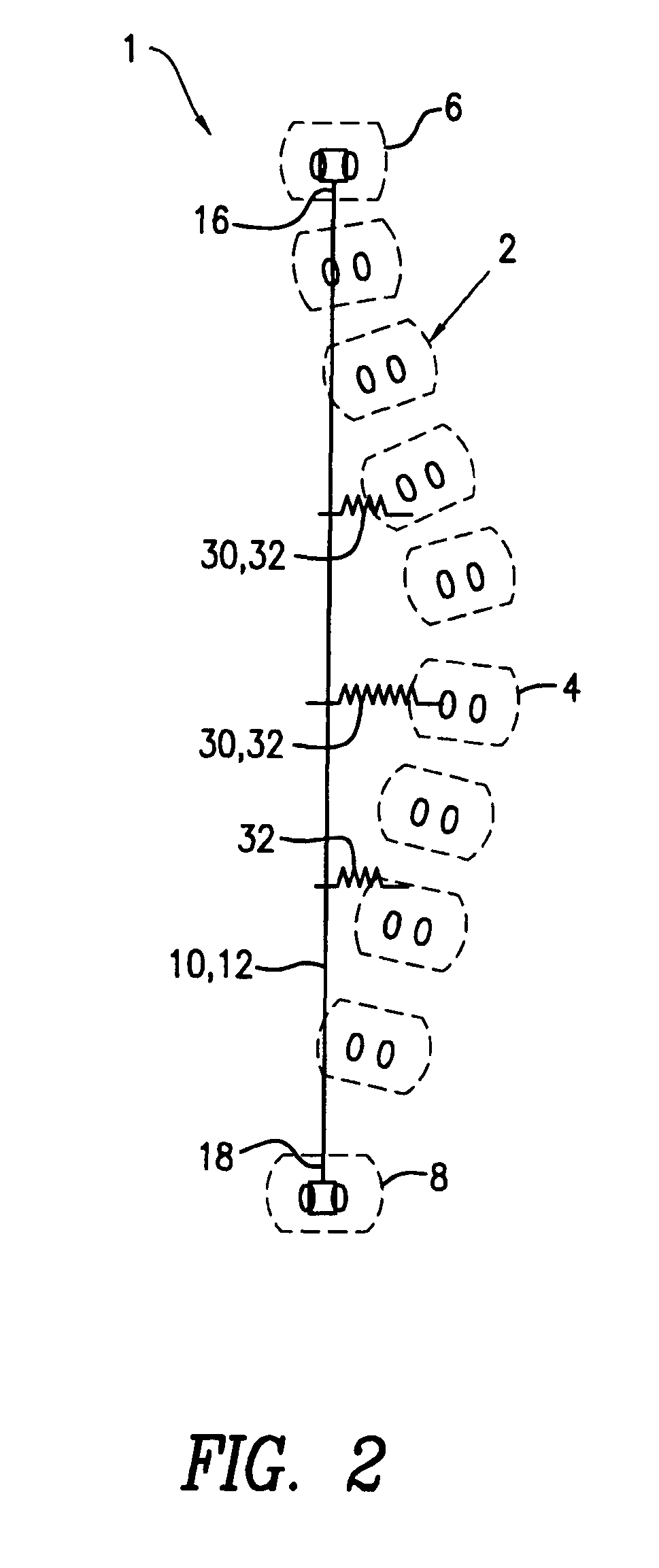
[0052]FIG. 2 shows the correction device 1, which is of a single support member type. Similar to the above, the support member 10 can be in a “C” or “S” shape, depending on the sagittal profile of the spine. In an exemplary embodiment, the support member 10 can be longitudinally aligned on the posterior side of the vertebrae. In another exemplary embodiment, the support member 10 can be disposed on the deformed spine 2 extending between a proximal vertebra 6 and a distal vertebra 8. The support member 10 can be mounted onto the spine 2 to provide a support for the correction device 1. In an exemplary embodiment, such as shown in FIG. 2, the two ends 16 and 18 of the support member 10 can be fixed to the proximal vertebra 6 and the distal vertebra 8. In another exemplary embodiment, the support member 10 can be secured to multiple sections of the deformed spine 2.

[0053]One or more anchor members 30 can be used to join the support member 10 with the deformed spine portion 4. Similar t...

third embodiment

[0055]FIG. 3 shows the correction device 1, which is of a dual support member type. The correction device 1 can comprise first and second support members 10a and 10b, such as in the form of “C” or “S” shaped supporting rods 12a and 12b. The support members 10a and 10b can be disposed in various positions in relation to the deformed spine 2. In one exemplary embodiment, at least one of the support members 10a and 10b can be longitudinally aligned on the posterior side of the spine 2. In another exemplary embodiment, the first and second support members 10a and 10b can fit into the concave and convex sides of the deformed spine portion 4, respectively. If desired, one or more cross-linking elements 40 can be provided to connect between the support members 10a and 10b, such as shown in FIG. 3.

[0056]The support members 10a and 10b can be secured to the deformed spine 2 in various manners. In one exemplary embodiment, the support members 10a and 10b can extend from a proximal vertebra 6 ...


PUM


Abstract

The present invention relates generally to a device of and a method for correcting spinal deformities, such as scoliosis and kyphosis. The invention employs the superelasticity or pseudoelasticity, such as found in a nickel-titanium alloy, to provide a continuous, predictable, and controllable correction force and to achieve a gradual and full correction. The correction force can be exerted on the deformed spine either at the time of the spine surgery or after the surgery or both, to afford a full or substantially full correction. The continuous and controllable correction force of the present invention is safer than an instantaneous and large correction force applied only at the time of surgery. Additionally, the continuous and controllable correction force is capable of gradually and fully correcting the spinal deformities without any post-operative manipulation of the correction device or re-operation.

Description

CROSS-REFERENCE TO RELATED APPLICATION[0001]This application claims the benefit of U.S. Provisional Application No. 60 / 406,019 filed Aug. 25, 2002.FIELD OF THE INVENTION[0002]The present invention generally relates to a device for and a method of correcting spinal deformities. In particular, the present invention relates a device for and a method of gradually correcting spinal deformities.BACKGROUND OF THE INVENTION[0003]Various correction systems have been used to correct spinal deformities. For example, the Harrington system, introduced in the early 1950s, employs a distraction rod on the concave side of the deformed spine. The use of the Harrington system and spinal fusion in treating idiopathic scoliosis was found useful for both single and double thoracic contours. However, a loss of lumbar lordosis, or the “flatback” effect, can occur when using the Harrington system along with distraction over the lumbar spine. This effect could be countered by segmental wiring (e.g., sublami...

Claims


Application Information

Patent Timeline
Patent Type & Authority Patents(United States)
IPC IPC(8): A61B17/70A61B17/00
CPCA61B17/7001A61B17/7031A61B2017/00867
Inventor CHEUNG, KENNETH M.YEUNG, KELVIN W. K.CHUNG, CHI YUENLU, WILLIAM W.
Owner HONG KONG UNIV OF
Why Eureka
Try Eureka