Power transmission mechanism and vehicle

a transmission mechanism and power technology, applied in the direction of electric propulsion mounting, couplings, transportation and packaging, etc., can solve the problems of vibration or abnormal noise of the vehicle, and achieve the effect of suppressing vibration and abnormal noise caused by the induced thrust for

Pending Publication Date: 2022-11-17
NTN CORP
View PDF0 Cites 0 Cited by
  • Summary
  • Abstract
  • Description
  • Claims
  • Application Information

AI Technical Summary

Benefits of technology

[0014]According to the present invention, the vibration and abnormal noise caused by the induced thrust force can be effectively suppressed.

Problems solved by technology

When these induced thrust forces resonate with an engine, a transmission, or mounting means of a differential device, this causes vibration or abnormal noise of the vehicle.

Method used


Image

  • Power transmission mechanism and vehicle
  • Power transmission mechanism and vehicle
  • Power transmission mechanism and vehicle

Examples


Embodiment Construction

[0022]Hereinafter, embodiments of the present invention are described with reference to the accompanying drawings. In the drawings for describing the present invention, constituent elements such as members and constituent parts having the same function or shape are denoted by the same reference numerals as long as they can be discriminated, and the description thereof is omitted.

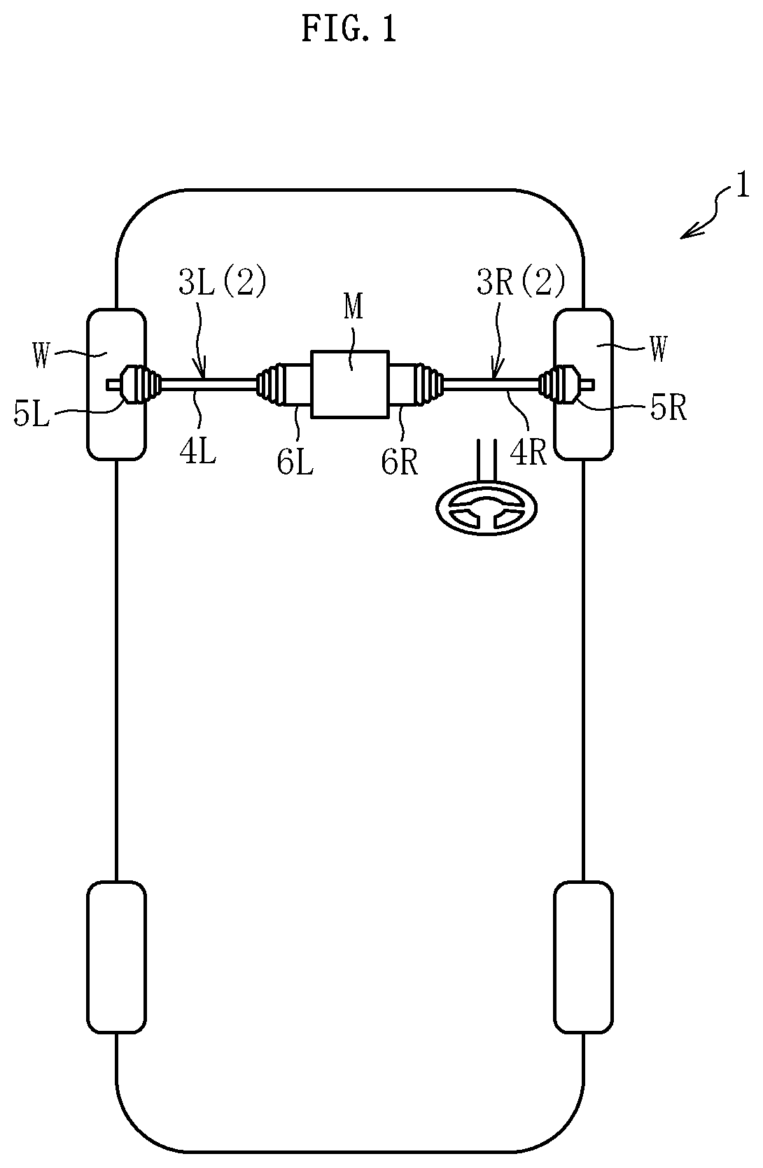
[0023]FIG. 1 illustrates a schematic configuration of a power transmission mechanism mounted on an electric vehicle.

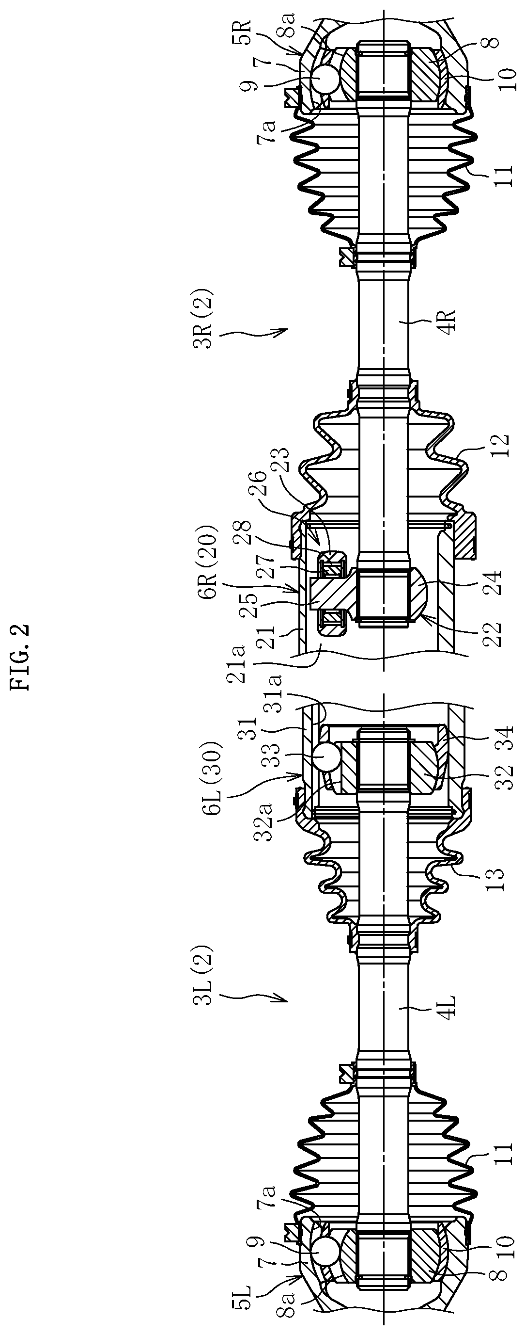
[0024]An electric vehicle 1 illustrated in FIG. 1 is a front wheel drive type motor-driven vehicle. The electric vehicle 1 includes left and right drive shafts 3L and 3R as a power transmission mechanism 2 that transmits the rotational torque of an electric motor M as a drive source to left and right front wheels W as drive wheels. The drive shafts 3L and 3R include intermediate shafts 4L and 4R, outboard side (vehicle outer side) fixed type constant velocity universal joints 5L and 5R connecte...


PUM


Abstract

A power transmission mechanism (2) includes left and right drive shafts (3L, 3R) that transmit rotational torque from a drive source to drive wheels provided on left and right sides of a vehicle. In the right drive shaft (3R) and the left drive shaft (3L), the numbers of rolling elements (23, 33) included in plunging type constant velocity universal joints (6L, 6R) are different from each other.

Description

TECHNICAL FIELD[0001]The present invention relates to a power transmission mechanism and a vehicle.BACKGROUND ART[0002]As a power transmission mechanism that transmits rotational torque from a drive source such as an engine or an electric motor mounted on a vehicle to left and right drive wheels, there is used a drive shaft including an outboard-side constant velocity universal joint arranged on the drive wheel side, an inboard-side constant velocity universal joint arranged on the opposite side to the drive wheel side, and an intermediate shaft connecting both the constant velocity universal joints together.[0003]Normally, as the constant velocity universal joint on the outboard side, a fixed type constant velocity universal joint is used which takes a large operating angle but is not displaced in the axial direction. On the other hand, as the constant velocity universal joint on the inboard side, a plunging type constant velocity universal joint is used which has a relatively smal...

Claims


Application Information

Patent Timeline
Patent Type & Authority Applications(United States)
IPC IPC(8): F16D3/2245B60K17/22
CPCF16D3/2245B60K17/22B60K2001/001F16D3/20F16D3/227F16D3/205Y02T10/72B60L15/2054F16D3/2055B60K17/24
Inventor KATOU, TAKUYATERADA, KENJIKAWASAKI, YASUNORI
Owner NTN CORP
Why Eureka
Try Eureka