Scrolling Device

a technology of graphical objects and buttons, applied in the direction of cathode-ray tube indicators, instruments, electric digital data processing, etc., can solve the problems of slow and cumbersome, inconfigurable, and inability to provide x-scrolling and z-scrolling, so as to increase the graphical object's scrolling rate and increase the pressure placed on the button

Inactive Publication Date: 2009-03-26
LOGITECH EURO SA
View PDF21 Cites 13 Cited by
  • Summary
  • Abstract
  • Description
  • Claims
  • Application Information

AI Technical Summary

Benefits of technology

[0009]According to another embodiment, an input device is provided that includes a control device, such as a joystick. The joystick is configured to control scrolling of graphical objects displayed on a display. Scrolling rates of graphical objects may be increased or decreased with increasing or decreasing forces placed on the joystick by a user.
[0011]According to another embodiment, a control device is provided that includes a force feedback module configured to place programmable feedback forces on a scroll wheel, such that the feedback forces (e.g., ratcheting forces) are generated synchronous with encoded scroll signals. Such control device reduces problems associated with synchronizing mechanical feedback generated by the scroll wheel with encoded scroll signals. According to some embodiments, the number of ratcheting steps are programmable (i.e., number of ratcheting forces per turn of the scroll wheel are controllable), or the ratcheting forces may be suppressed.
[0017]According to another embodiment, a control device is provided that includes first and second control buttons. The control button are configured to control scrolling and a scrolling rate of graphical objects displayed on a monitor. One of the buttons may be configured to control scrolling in a first direction (e.g., positive y-axis), and the other button may be configured to control scrolling in a second direction (e.g., negative y-axis). Scrolling rates of the graphical object may be increased with increasing pressures placed on the buttons.
[0018]According to another embodiment, a control device is provided that includes a set of friction pads disposed on a lower surface of the control device and are configured to slide on a surface (e.g., desktop, mousepad, etc.). At least two of the friction pads in the set are coupled to forces sensors that are configured to provide detected force information to a micro-controller running a micro-controller program that is configured to place the control device in a “sleep mode” (i.e., a reduced current consumption mode), leave the control device in a “power up mode” (i.e., normal operation mode), or to transition the control device from the sleep mode to the power up mode based on the detected force information provided by the force sensors.

Problems solved by technology

Typical control devices, such as mice and track balls, configured to control graphical objects displayed on monitors typically provide y-scrolling but fail to provide for x-scrolling and z-scrolling.
Such control of x-scrolling requires a number of user interactions with a control device and a computer, and as such tends to be slow and cumbersome.

Method used


Image

  • Scrolling Device
  • Scrolling Device
  • Scrolling Device

Examples


Embodiment Construction

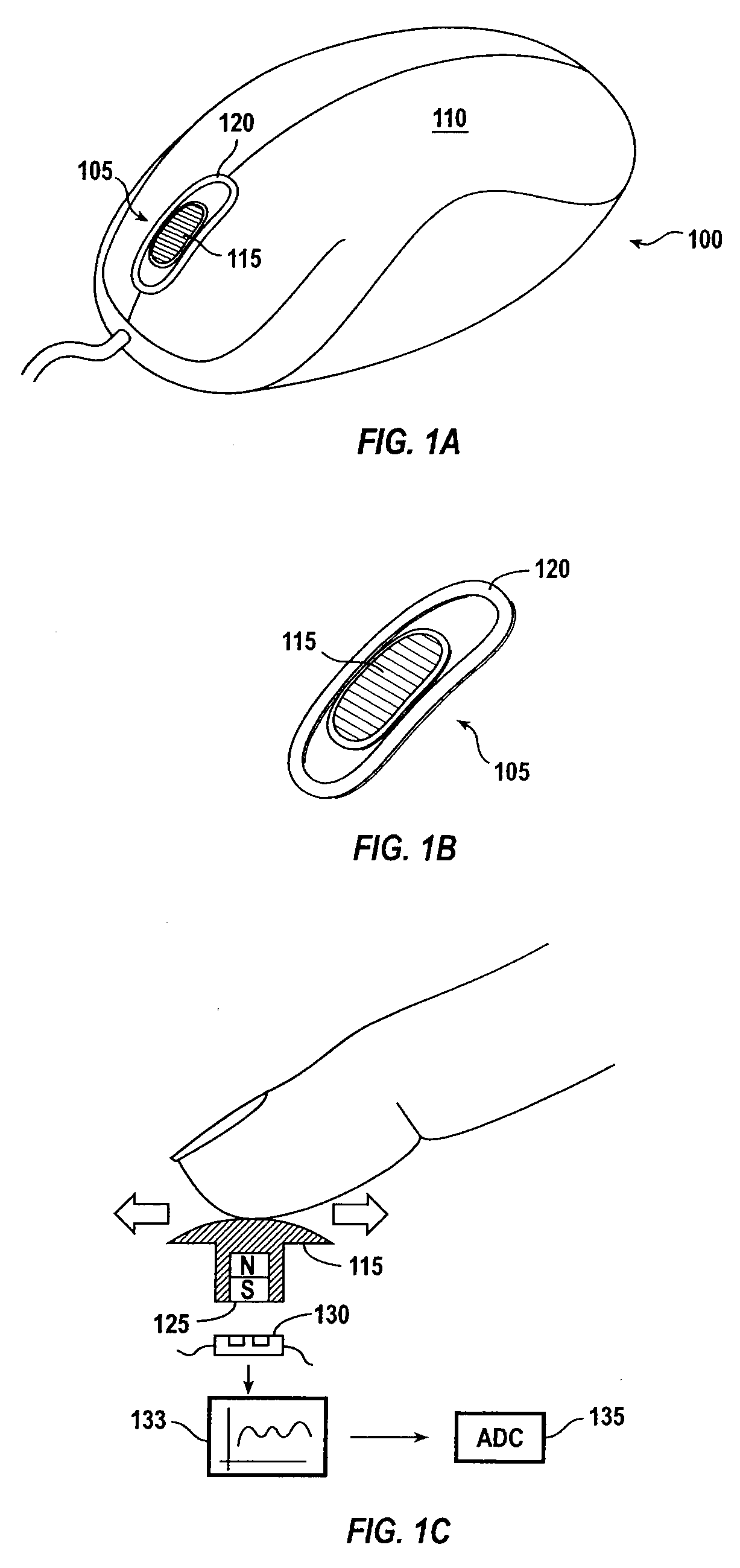
[0045]FIG. 1A is a simplified schematic of a control device 100 according to an embodiment of the present invention. Control device 100 may be a mouse type device or the like. Control device 100 includes a slider mechanism 105 disposed in a case 110. The slider mechanism includes a slider button 115 configured to slide forward and backward, for example, under the force of a user's finger. The slider button is configured to slide in a guide 120 (see FIG. 1B) that generally limits sideways motion of the slider and guides the slider in forward and backward travel. The slider may be configured to control graphical object displayed on a computer monitor or the like. For example, the slider may be configured to control scrolling of a pointer, cursor, screen or the like. A variety of encoding means may be used to encode forward and backward signals from the sliders forward and backward travel. For example, a magnet 125 (see FIG. 1C) may be disposed in a bottom portion of the slider and, a ...


PUM


Abstract

A control device is provided for controlling scrolling of a graphical object displayed on a computer monitor. The control device includes a housing; and a slider device disposed at a front portion of the housing configured to control scrolling of the graphical object on the monitor.

Description

CROSS REFERENCE TO RELATED APPLICATIONS[0001]This application is a divisional application of, and claims priority to, U.S. patent application Ser. No. 10 / 884,543, filed Jul. 2, 2004, titled “Scrolling Device,” of Patrick Monney et al., and which is incorporated by reference herein in its entirety for all purposes.[0002]This application is related to U.S. patent application Ser. No. ______ (attorney docket no. 09623C-046920US), filed Sep. 24, 2008, titled “Scrolling Device,” of Patrick Monney et al., and which is incorporated by reference herein in its entirety for all purposes.BACKGROUND OF THE INVENTION[0003]The present invention relates generally to control devices and control methods. More particularly the present invention relates to control devices for controlling graphical objects displayed on a display.[0004]Typical control devices, such as mice and track balls, configured to control graphical objects displayed on monitors typically provide y-scrolling but fail to provide for...

Claims


Application Information

Patent Timeline
Patent Type & Authority Applications(United States)
IPC IPC(8): G09G5/08G06F3/033
CPCG06F3/03543G06F3/0312
Inventor MONNEY, PATRICKBIDIVILLE, MARCJUNOD, PHILIPPEMERMINOD, BAPTISTEMERMINOD, ANTOINEAMBUEHL, ROLFTIPHANE, GUYSOMMER, RENEKEHLSTADT, FLORIANPLANCHEREL, LAURENT
Owner LOGITECH EURO SA
Why Eureka
Try Eureka