Gas Turbine Engine System for Modulating Flow of Fan By-Pass Air and Core Engine Air

a technology of gas turbine engine and by-pass air, which is applied in the direction of machines/engines, jet propulsion plants, etc., can solve the problems of pressure drop in both by-pass air and core fuel air mixture within the augmentor, and substantial thrust loss from the fan air stream, so as to maximize the cooling of the convergent wall and minimize the effect of thrust loss

Active Publication Date: 2016-06-02
RTX CORP
View PDF12 Cites 3 Cited by
  • Summary
  • Abstract
  • Description
  • Claims
  • Application Information

AI Technical Summary

Benefits of technology

[0019]It is a more specific purpose of the present disclosure to provide a gas turbine engine system for modulating flow of fan by-pass air and core engine air that minimizes loss of thrust generated by the rotating fan and combusted fuel, and that maximizes cooling of a convergent wall of a convergent nozzle section of the gas turbine engine as flow of fan by-pass and core engine air are modulated. These and other purposes and values of the present disclosure will become apparent in the following detailed description and the accompanying drawings.

Problems solved by technology

Many problems are associated with varying flow of by-pass fan air into the core engine.
This approach produces a substantial decrease in available thrust from both the fan and augmentor by having the by-pass air turn at ninety-degrees from within the by-pass duct into the augmentor, thereby disrupting linear flow of the exhaust stream which results in a pressure drop in both the by-pass air and core fuel air mixture within the augmentor.
Additionally, substantial thrust may be lost from the fan air stream because complex actuators partially within the duct are required to rotate the sleeve valve.
The same problems arise in U.S. Pat. No. 5,307,624 that issued on May 3, 1994 to Even-Nur et al., wherein a different actuator is utilized as part of a valve to direct by-pass air from a by-pass duct into an entry of an augmentor.
The fairing structure of Lace produces a very substantial loss of thrust in the by-pass fan duct, and involves a high degree of complexity in the actuating mechanism.

Method used


Image

  • Gas Turbine Engine System for Modulating Flow of Fan By-Pass Air and Core Engine Air
  • Gas Turbine Engine System for Modulating Flow of Fan By-Pass Air and Core Engine Air
  • Gas Turbine Engine System for Modulating Flow of Fan By-Pass Air and Core Engine Air

Examples


Embodiment Construction

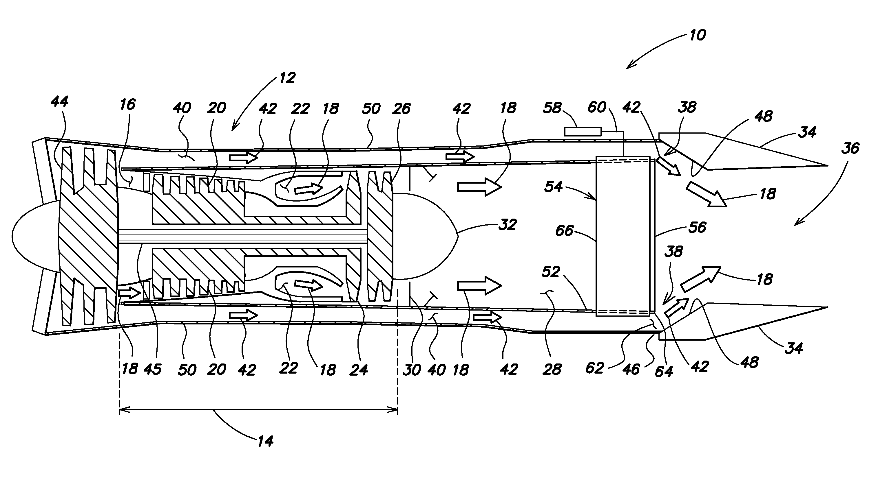
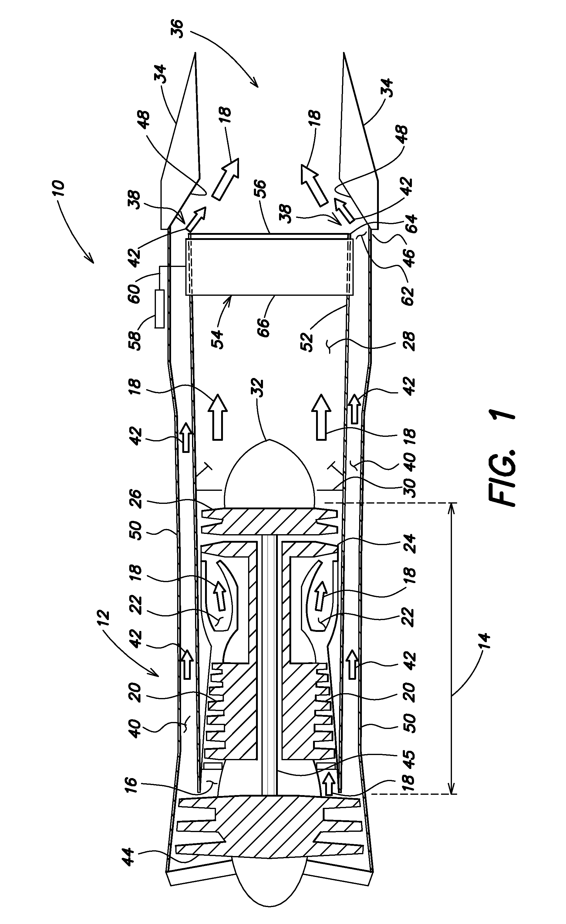
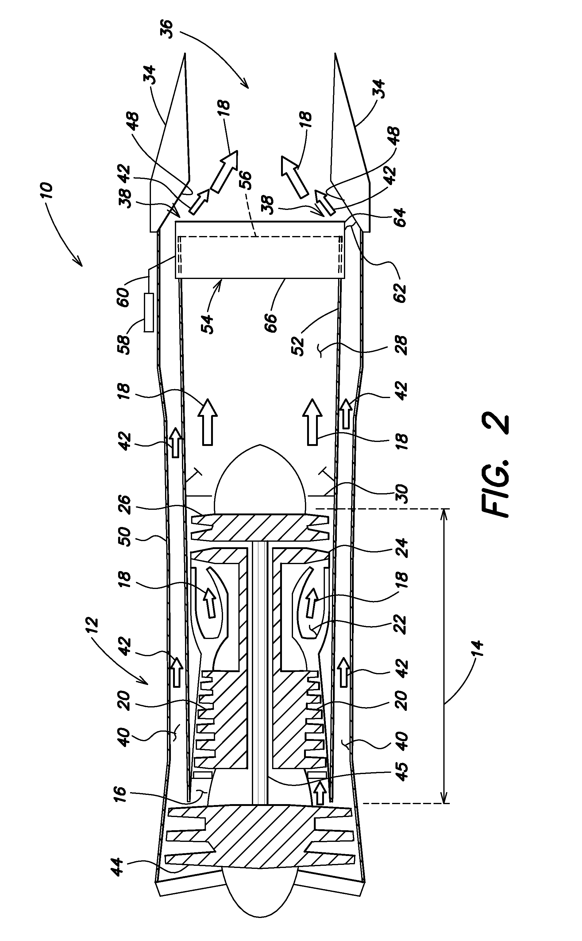
[0024]Referring to the drawings in detail, FIG. 1 shows a simplified schematic cross-sectional drawing showing a gas turbine engine system for modulating flow of fan by-pass air and core engine air constructed in accordance the present disclosure and generally designated by the reference numeral 10. The system includes a gas turbine engine 12 having an engine core 14 defining passageways 16 for directing flow of the core engine air (represented by flow arrows designated with reference numeral 18) sequentially through a compressor 20, a combustor 22 wherein the air is combusted with a fuel. The combusted engine core air then passes through and rotates a high pressure turbine 24, a low pressure turbine 26, and then passes out of the engine core 14. Optionally, the engine core air 18 may then pass through an augmentor 28 (as shown in FIG. 1) or “afterburner”, wherein additional fuel and air are admitted and ignited by an ignition ring 30 to produce additional thrust, as commonly found ...


PUM


Abstract

The system (10) provides a modulator ring (54) secured adjacent an exhaust end (56) of an inner wall of a by-pass fan air duct (40) and secured adjacent a convergent nozzle section (38) of the engine wherein flow of by-pass fan air (42) and core engine air (18) converge within an exhaust nozzle (34), The modulator ring (54) may be actuated to extend beyond the exhaust end (56) of the duct (40) to decrease air passage (62) forcing more air into the core engine (14) for greater thrust from the core engine (14) with minimal loss of thrust from the by-pass fan air (42). The modulator ring (54) stay alternatively rotate to uncover trailing-edge slots in the exhaust end (56) of the duct to also modulate flow rates of by-pass fan air (42) into the convergent nozzle section (38),

Description

CROSS-REFERENCE TO RELATED APPLICATION[0001]This Application claims the benefit of U.S. Provisional Patent Application Ser. No. 61 / 843,209 that was filed on Jul. 5, 2013, entitled “GAS TURBINE ENGINE SYSTEM FOR MODULATING FLOW OF FAN BY-PASS AIR AND CORE ENGINE AIR.”TECHNICAL FIELD[0002]The present disclosure relates to a gas turbine engine system for changing relative amounts of fan by-pass and core engine air passing through a by-pass fan air duct and an engine core to increase engine operating efficiencies through varying flight conditions.BACKGROUND ART[0003]In the field of gas turbine engines it is known that thrust is generated by combustion of a pressurized fuel and air mixture within a combustor of an engine core and discharge of the expanded, combusted fuel air mixture through a high-pressure and low-pressure turbine and out of the core engine through a variable discharge exhaust nozzle. Thrust is also generated by a rotating fan at an entry end of the engine. The fan is ro...

Claims


Application Information

Patent Timeline
Patent Type & Authority Applications(United States)
IPC IPC(8): F02K1/08F02K1/15
CPCF02K1/15F02K1/08
Inventor LOVETT, JEFFREY A.
Owner RTX CORP
Why Eureka
Try Eureka