Self-regulating gas generator and method

a gas generator and self-regulation technology, applied in the direction of machines/engines, process and machine control, instruments, etc., can solve the problems of power sources having their own drawbacks, and achieve the effect of increasing or decreasing gas production rates and long catalyst li

Active Publication Date: 2016-12-20
ENCITE LLC
View PDF32 Cites 1 Cited by
  • Summary
  • Abstract
  • Description
  • Claims
  • Application Information

AI Technical Summary

Benefits of technology

[0004]A self-regulating, portable, gas generator, or method of gas generation corresponding thereto, according to the principles of the present invention generates gas for diverse portable power generation applications in a manner that automatically increases or decreases gas production rates in response to usage requirements. The self-regulating gas generator provides portability and has safety characteristics suitable for military, industrial, and consumer applications. Some embodiments of the self-regulating gas generator exhibit long lifespan of catalyst used to generate gas from a chemical supply based on the self-regulating features.
[0009]The element(s) may be coated with the gas permeable structure, covered with the gas permeable structure, or integrated into the gas permeable structure. The element(s) may also include a non-catalytic portion, which may be located along the length of the element(s). In the case of the element(s) being operated as a piston, the non-catalytic portion may be located at an end of the piston. The element(s) may be adapted to position the catalytic and non-catalytic portions with respect to the chemical supply so no catalyst is exposed to the chemical supply. Such a position discontinues decomposition of the chemical supply. The gas generator may also include a “wipe” that is adapted to dislodge products from the element(s) so as not to accumulate the products or other materials on the element(s), thereby increasing the lifespan of the catalyst or the element(s) themselves.
[0016]Some of the gas generator embodiments described herein include some or all of the following safety and operational features that make it useful for many applications. These features in no particular order may include: automatic gas production sufficient to match consumption rates, compact or large design, orientation insensitivity, high level of system safety, and automatic limiting of hydrogen gas or other gas production so that the gas generator cannot have a runaway reaction. For example, if hydrogen gas pressures become too large (i.e., too much hydrogen gas is being produced), the system may automatically shut itself down.
[0023]In one example of the bang-bang embodiment, the element and catalyst are coupled to each other, e.g., the catalyst is in or on the element in a body-facing direction. Alternatively, the catalyst may be coupled to the body, e.g., in or on the body in a chamber-facing direction. In both embodiments, the element may be configured to move relative to the body in a translational or rotational motion. It should be understood that the catalyst may still further alternatively be applied to an insert, and the insert may be affixed to the body or the element, where using an insert may be useful for quick replacement of catalyst while maintaining the same body or body and element, respectively, across catalyst replacement.
[0025]In still another example bang-bang embodiment of the gas generating device, the device includes a forcer, such as a spring, coupled to the element to exert a force to enable the element to move as a function of the pressure internal to the chemical supply chamber relative to pressure in the reference pressure chamber, with the forcer positioned in the reference pressure chamber. A detent may be employed at an interface of the element and body of the device to provide a small resistance that can be overcome by a sum of forces on the element above or below the same or different thresholds. The detent can be set to provide hysteresis to maintain a position or orientation of the element relative to the body (i.e., to maintain the ON state or OFF state of the device) absent a threshold change in pressure differential between the chemical supply chamber and reference pressure chamber.

Problems solved by technology

Each of these power sources has its own drawbacks.
One such drawback is in the form of pollution, where AC power generation plants, gas generators, and batteries produce respective environmentally unfriendly by-products (e.g., ozone destroying gases and battery acid waste).

Method used


Image

  • Self-regulating gas generator and method
  • Self-regulating gas generator and method
  • Self-regulating gas generator and method

Examples


Embodiment Construction

[0042]A description of preferred embodiments of the invention follows.

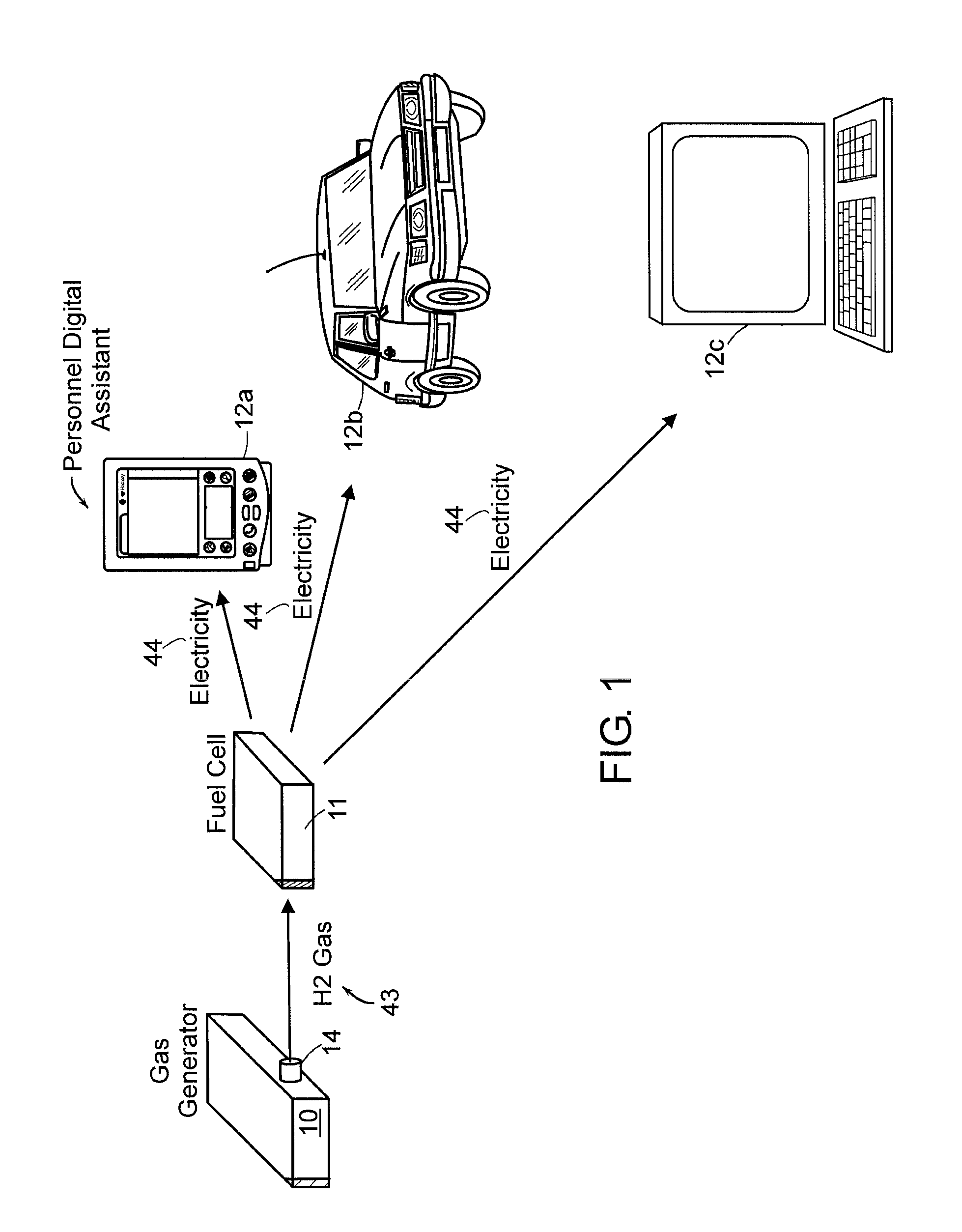
[0043]FIG. 1 is a graphical diagram of a fuel cell application in which a gas generator 10 according to the principles of the present invention may be employed. In the fuel cell application, the gas generator 10 generates and delivers hydrogen gas to a fuel cell 11. The fuel cell 11 reacts the hydrogen gas and oxygen to produce electricity 44, as well known in the art. The fuel cell 11 provides the electricity 44 to an electricity-consuming device, such as a personal entertainment device 12a (e.g., MP3 player), remote controlled car 12b, or portable computer 12c. Other fuel cell applications include military electronics, industrial electronics (e.g., printing presses), or consumer electronics (e.g., cellular telephones, Personal Digital Assistants (PDA's), and so forth).

[0044]Generally, a fuel cell consumes hydrogen gas at a rate depending on the power its generating. An example fuel cell is described in U.S. Pat....


PUM

PropertyMeasurementUnit
gas pressureaaaaaaaaaa
volumeaaaaaaaaaa
pressureaaaaaaaaaa

Abstract

A self-regulating gas generator that, in response to gas demand, supplies and automatically adjusts the amount of gas (e.g., hydrogen or oxygen) catalytically generated in a chemical supply chamber from an appropriate chemical supply, such as a chemical solution, gas dissolved in liquid, or mixture. In some embodiments, the gas generator may employ a piston, rotating rod, or other element(s) to expose the chemical supply to the catalyst in controlled amounts. In another embodiment, the self-regulating gas generator uses bang-bang control, with the element(s) exposing a catalyst, contained within the chemical supply chamber, to the chemical supply in ON and OFF states according to a self-adjusting duty cycle, thereby generating and outputting the gas in an orientation-independent manner. The gas generator may be used to provide gas for various gas consuming devices, such as a fuel cell, torch, or oxygen respiratory devices.

Description

BACKGROUND OF THE INVENTION[0001]Presently, nearly all military, industrial, and consumer electronics are powered by conventional sources—AC wall outlets, gas generators, or disposable or rechargeable batteries. Each of these power sources has its own drawbacks. One such drawback is in the form of pollution, where AC power generation plants, gas generators, and batteries produce respective environmentally unfriendly by-products (e.g., ozone destroying gases and battery acid waste).[0002]Fuel cells have been proposed as an environmentally friendly solution to this problem. To be adopted as a solution, however, fuel (e.g., hydrogen gas) must be easily and safely accessible at a price competitive with its conventional counterparts.[0003]Portable gas generators can safely produce high purity gas on demand. Such generators are useful in providing hydrogen gas as a fuel for fuel cells or other types of gases for other gas utilizing devices. In the case of generating hydrogen gas for fuel ...

Claims


Application Information

Patent Timeline
Patent Type & Authority Patents(United States)
IPC IPC(8): B01J7/00C01B13/02C01B3/36C01B3/06
CPCB01J7/00C01B3/065C01B13/02Y02E60/362Y02E60/36
Inventor MARSH, STEPHEN A.PARKER, DONALD M.PINTAURO, PETER N.
Owner ENCITE LLC
Why Eureka
Try Eureka