Reflow soldering method

a soldering method and reflow technology, applied in the direction of soldering apparatus, coupling device connection, manufacturing tools, etc., can solve the problems of not being able to mount certain other non-vertically approaching components, solder joints are often unsatisfactory, and further problems may aris

Inactive Publication Date: 2000-01-04
PLEXUS PROPERTY HLDG +2
View PDF3 Cites 70 Cited by
  • Summary
  • Abstract
  • Description
  • Claims
  • Application Information

AI Technical Summary

Problems solved by technology

Unfortunately, it has not been practical to mount certain other nonvertically approaching components such as edge connectors onto the circuit card with reflow soldering methods.
When reflow occurs, the solder joints are often unsatisfactory due possibly to shorting between pads, insufficient solder at the lead and pad interface, or solder balling.
In addition, as shown in FIGS. 2C to 2E, a further problem may arise.
When reflow occurs, the resulting solder bonds on both the primary and secondary sides are often unsatisfactory.
It can be seen, however, that this method is tedious and time consuming for the human operator.
Moreover, such manual soldering can lead to poor solder connections resulting from human error, as well as from inherent flaws in the soldering method.

Method used


Image

  • Reflow soldering method
  • Reflow soldering method
  • Reflow soldering method

Examples


first embodiment

5.3.1 A First Embodiment

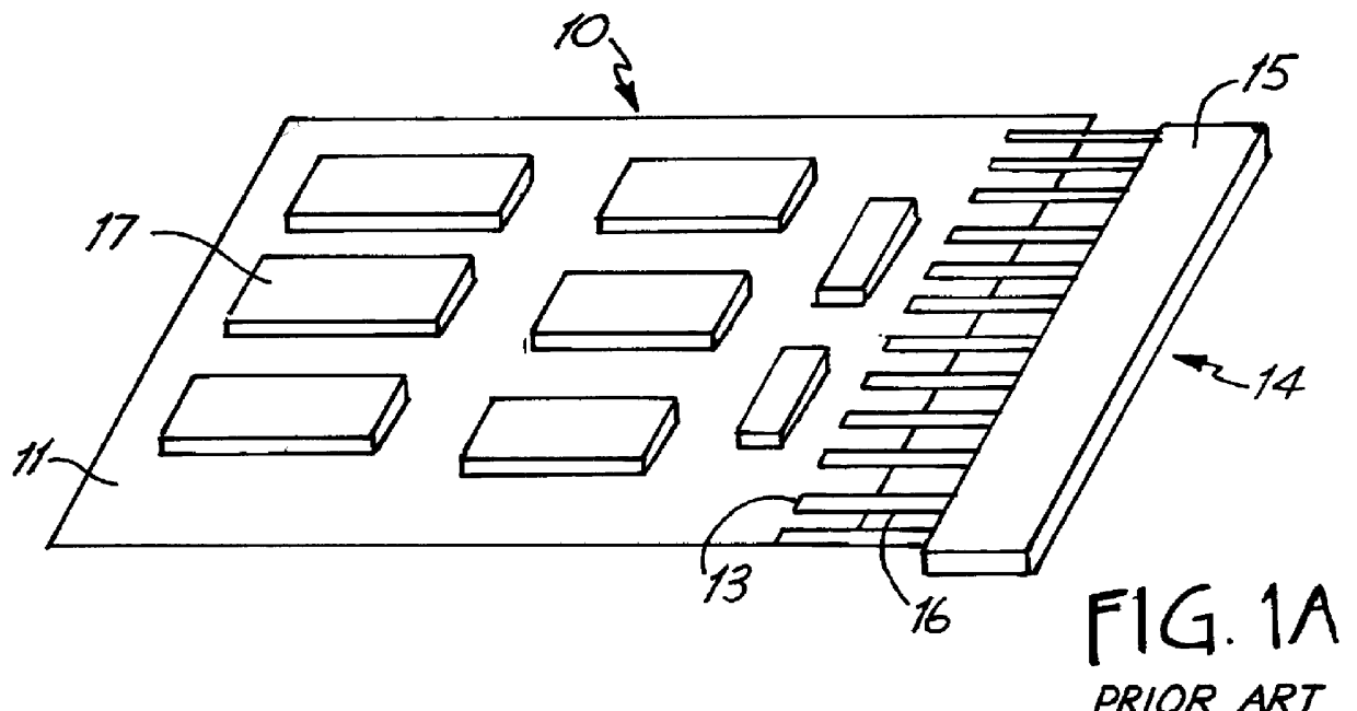
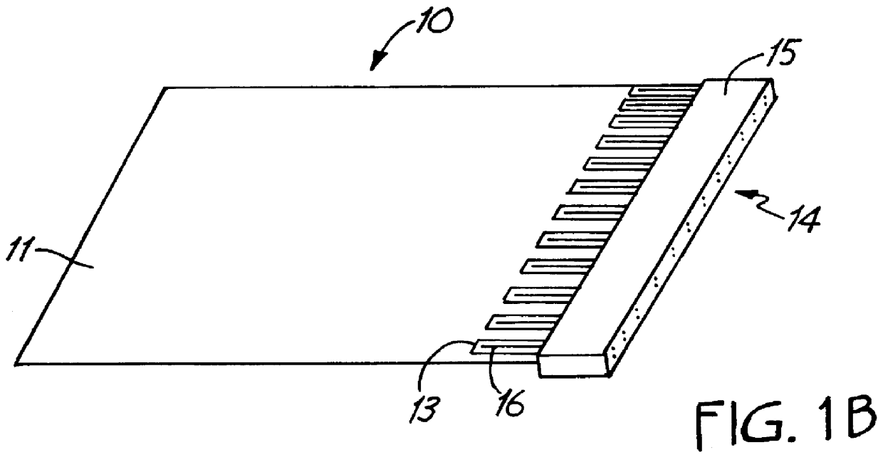
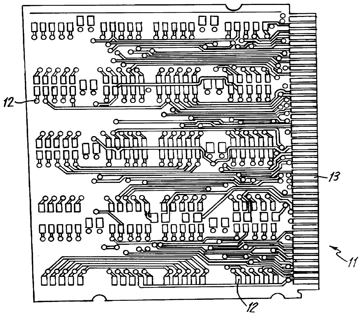
FIGS. 5A and 5B show one embodiment of a system 200 for reflowing connector(s) 14 to circuit card(s) 11 in a manner that is consistent with the present invention. System 200 includes conveyor oven 202 and mating pallet assembly 210. Mating pallet assembly 100 includes tray assembly 50 and mating pallet 100, which includes trigger switches 162A and 162B. Conveyor oven 202 has a conveyor belt 204 for transporting mating pallet assembly 100 through conveyor oven 202. Conveyor oven 202 further includes a trigger discharge mechanism 206 for initiating mating pallet 100 to mate the connectors 14 with circuit cards 11. As used hereinafter, a "mating pallet" is any apparatus or combination of apparatuses that is used to mate a nonvertically approaching device with the soldered surface(s) to which it is to be soldered. A "trigger discharge mechanism" is any mechanism that is used to initiate a mating pallet to mate the nonvertically approaching device with the solderi...


PUM

PropertyMeasurementUnit
eutectic temperatureaaaaaaaaaa
mating temperatureaaaaaaaaaa

Abstract

With the present invention, a reflow soldering method is provided for soldering a nonvertically approaching lead, which is part of a nonvertically approaching device (e.g, an edge connector), to a corresponding soldering surface (e.g., a pad on a circuit card) that includes solder. The soldering surface and solder are heated in an oven to melt the solder. While the solder is liquids, the nonvertically approaching lead is mated with the soldering surface as it is inserted into the solder. The soldering surface, solder, and nonvertically approaching lead are then cooled, and the solder solidifies to conductively mount the nonvertically approaching lead to the soldering surface.

Description

This application is related to and hereby incorporates by reference an application titled A REFLOW SOLDERING APPARATUS, filed on the same date herewith.1. TECHNICAL FIELDThe present invention relates generally to a soldering reflow method. In particular, the present invention relates to reflow soldering processes for soldering certain leaded devices to soldering surfaces.2. BACKGROUNDReflow soldering is a form of soldering that enables reflowable (e.g., surface mounted) components to be efficiently and effectively mounted to one or both side(s) of a circuit card. The term "circuit card" generally describes any substrate, with or without a component, for accommodating a circuit. A circuit card would include but is not limited to a printed circuit board ("PCB"), a printed circuit assembly ("PCA"), and a bread board. FIGS. 1A to 1C depict a circuit card assembly 10 having a circuit card 11, an edge connector 14, and reflowable components 17.The reflowable components 17 are soldered to ...

Claims


Application Information

Patent Timeline
Patent Type & Authority Patents(United States)
IPC IPC(8): B23K1/00H01R43/02H05K3/34
CPCB23K1/0016H01R43/0256H05K3/3405B23K2201/42H01R23/70H05K3/3494H05K2201/10189H05K2203/0475B23K2101/42H01R12/707H01R12/721
Inventor HOWELL, DAVID A.
Owner PLEXUS PROPERTY HLDG
Why Eureka
Try Eureka