Method and apparatus for surface conditioning

a surface conditioning and apparatus technology, applied in the direction of cleaning processes and apparatus, chemical apparatus and processes, semiconductor devices, etc., can solve the problems of non-uniform gas distribution, safety, waste disposal, cleanliness and cost, and additional damage and contamination of the substrate surface of aqueous chemical processes

Inactive Publication Date: 2000-01-18
FSI INTERNATIONAL INC
View PDF53 Cites 88 Cited by
  • Summary
  • Abstract
  • Description
  • Claims
  • Application Information

AI Technical Summary

Problems solved by technology

The liquid aqueous chemical processes have problems involving safety, waste disposal, cleanliness and cost, and these problems make the use of gaseous processes very attractive.
These types of processes have the disadvantage of causing additional damage and contamination of the substrate surface.
Processes of the type disclosed in Hall or Ligenza have the disadvantages of non-uniform gas distribution and of a static gas regime which does not allow the transport of contaminants and etching residues out of the reactor during the etch reaction.
Applicants have found that systems of the type directing a flow of gas which chemically reacts, with or without photochemic

Method used


Image

  • Method and apparatus for surface conditioning
  • Method and apparatus for surface conditioning
  • Method and apparatus for surface conditioning

Examples


Embodiment Construction

is hereafter described with specific reference being made to the drawings in which:

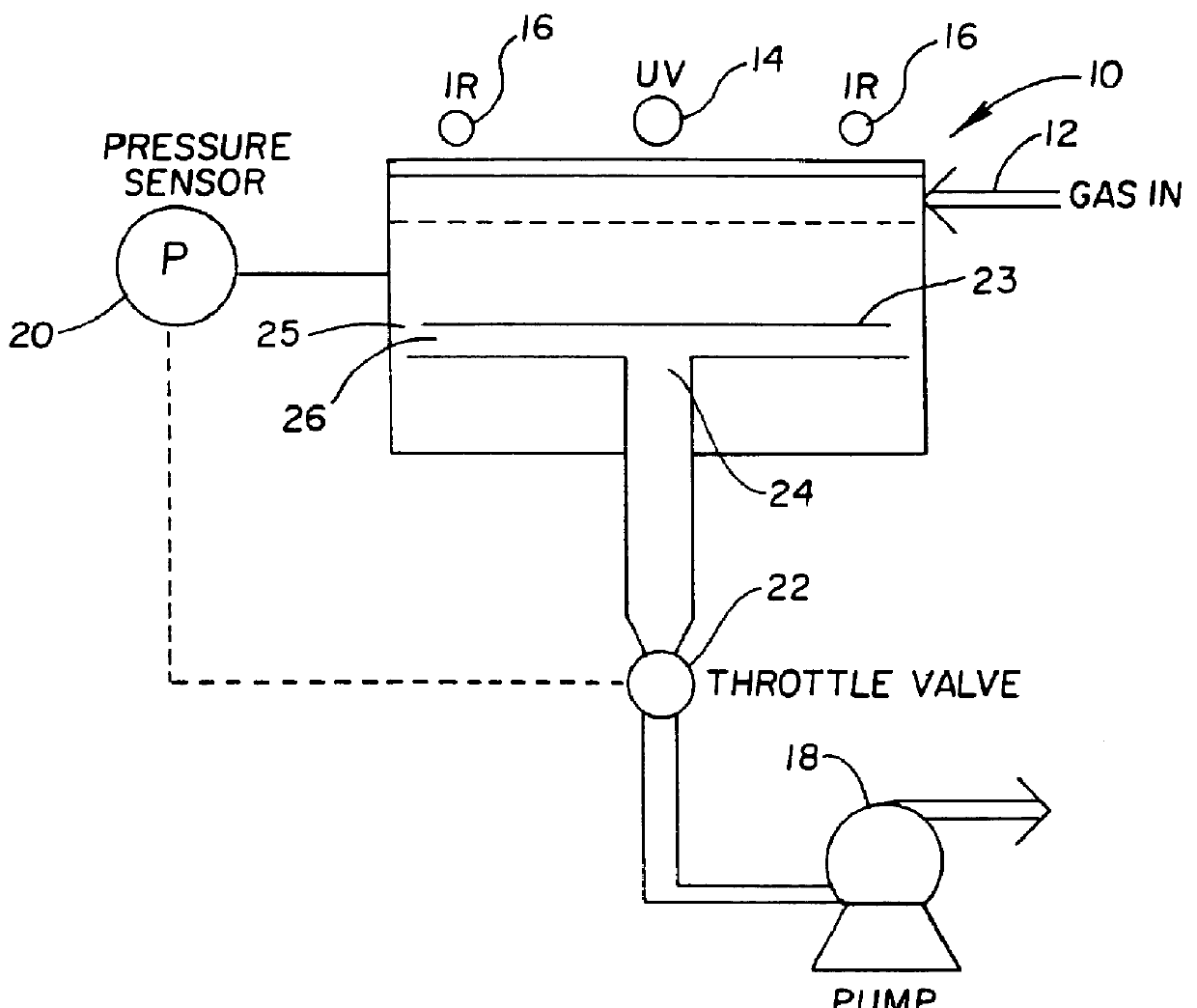
FIG. 1 is a schematic diagram of a first embodiment of the inventive apparatus;

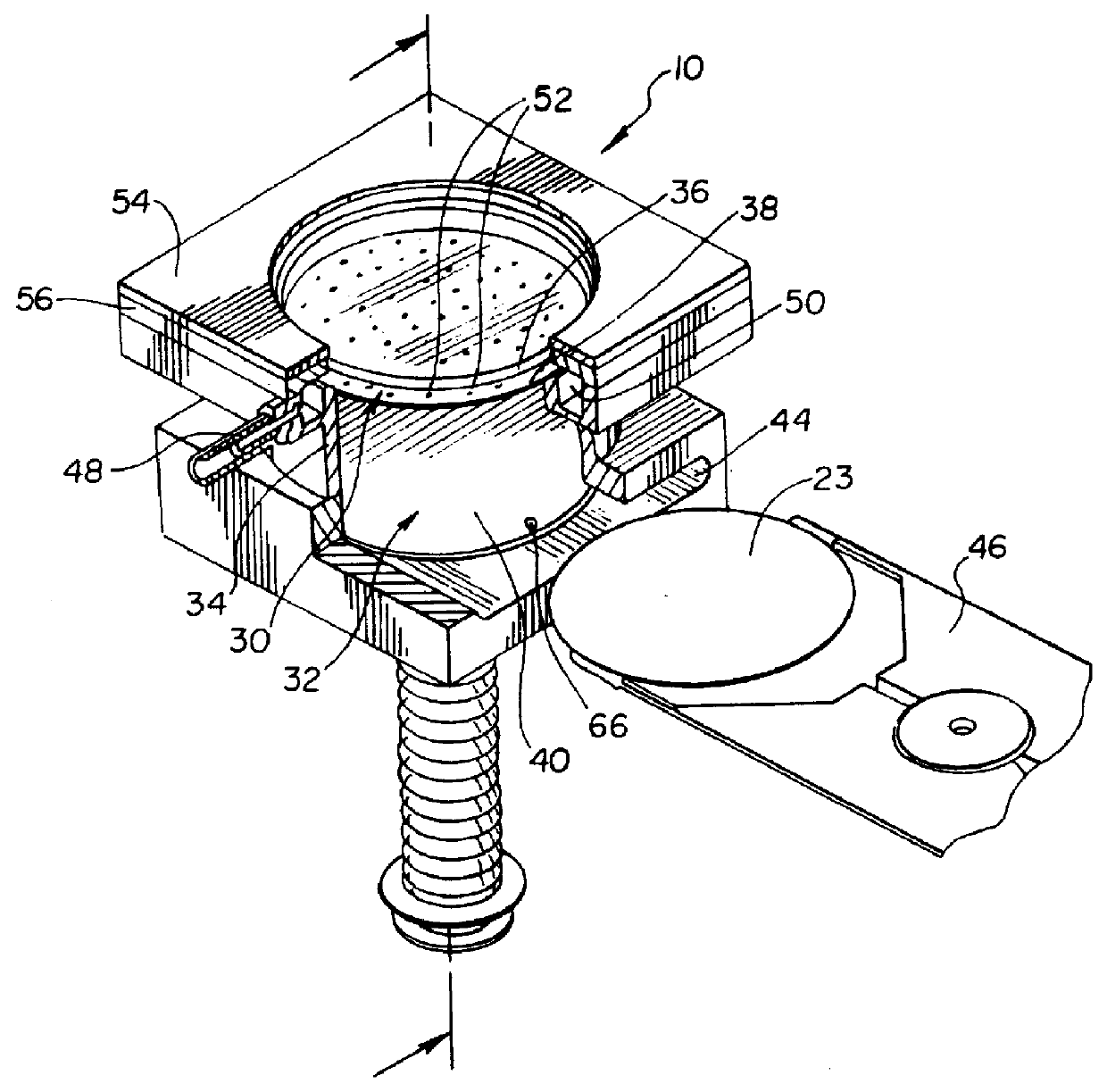
FIG. 2 is a front perspective view of the first embodiment of the invention with a portion cut away;

FIG. 3a is a cross sectional view of the first embodiment in the load position;

FIG. 3b is a cross sectional view of the first embodiment in the processing position;

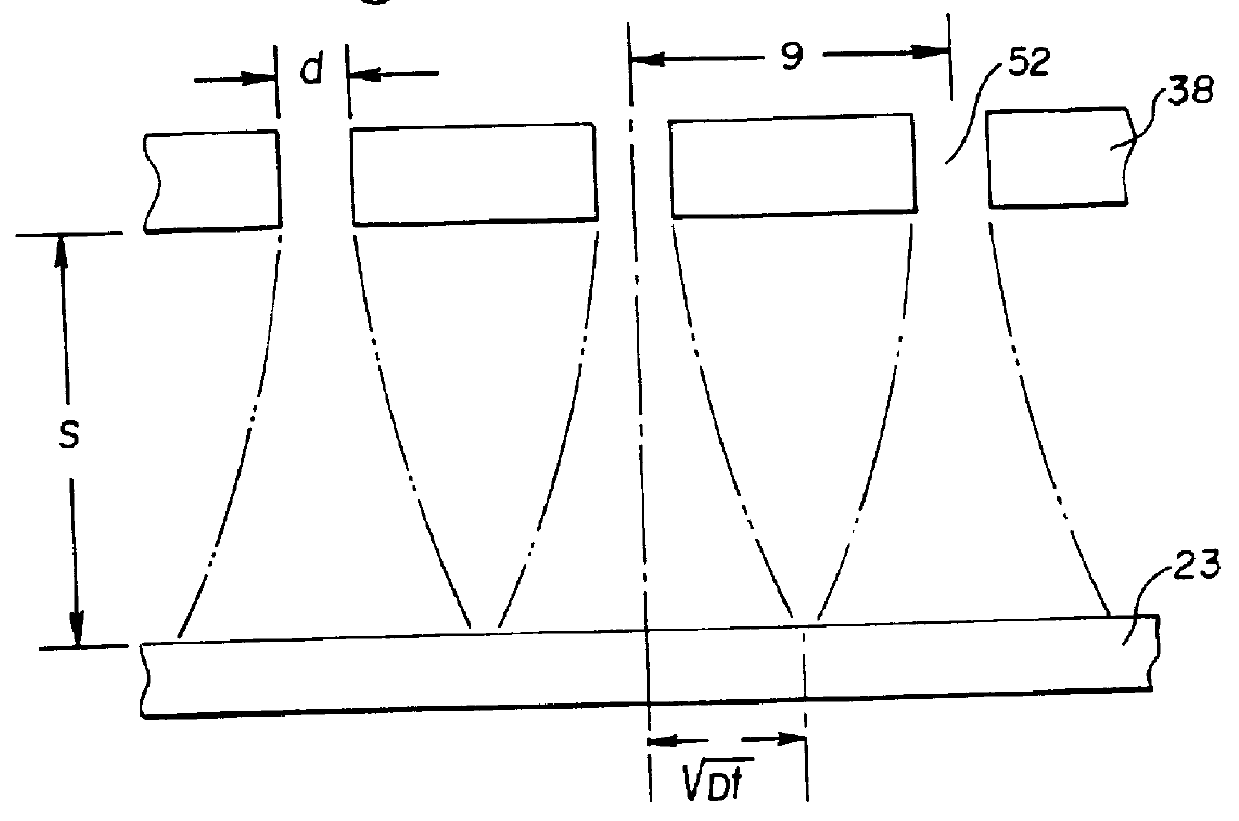
FIG. 4 is a schematic of the parameters for determining the diffusional mixing between the perforated plate and the substrate;

FIG. 5 is an exploded schematic view showing the flow of conditioning gas through the first embodiment;

FIG. 6 is an exploded schematic view of an alternate embodiment of the gas inlet showing the flow of conditioning gas through the apparatus;

FIG. 7a is a cross sectional view of an alternate embodiment of the apparatus, shown in the load position;

FIG. 7b is a cross sectional view of FIG. 7a shown in the processing position;

FIG. 8 is a cross ...


PUM

PropertyMeasurementUnit
Sizeaaaaaaaaaa
Sizeaaaaaaaaaa
Timeaaaaaaaaaa

Abstract

PCT No. PCT/US95/16649 Sec. 371 Date Sep. 2, 1997 Sec. 102(e) Date Sep. 2, 1997 PCT Filed Dec. 21, 1995 PCT Pub. No. WO96/19825 PCT Pub. Date Jun. 27, 1996Apparatus and process for conditioning a generally planar substrate, contained in a chamber isolatable from the ambient environment and fed with a conditioning gas which includes a reactive gas. The apparatus includes a support for supporting the substrate in the chamber, the substrate being in a lower pressure reaction region of the chamber. A gas inlet is provided for feeding conditioning gas into a gas inlet region of the chamber which is at a higher pressure than the lower pressure reaction region so that the pressure differential causes the conditioning gas to flow toward the surface of the substrate wherein the conditioning gas component will chemically react with and condition the substrate surface, both said higher and lower pressure regions operating in a viscous flow regime. The substrate is supported such that a pressure bias is created across the surface of the substrate so that the gas, after it has chemically reacted with the substrate surface, flows outward from where it has reacted, off the substrate toward the periphery of the chamber and out a peripheral or central underside exhaust outlet. Gas feed may be provided to one or both sides of the substrate and light activation of the substrate or conditioning gas may be provided on one or both sides.

Description

1. Field of the InventionThe present invention relates to an apparatus which provides for the conditioning of the surface of a substrate in a plasma-less gas phase environment. It finds particular application in etching, cleaning, or bulk stripping removal of films or contaminants from the surface of a semiconductor wafer for use in the fabrication of integrated circuits.2. Description of the Related ArtThe traditional standard for surface contamination removal in the semiconductor industrv is the RCA clean which uses liquid aqueous chemicals. Highly selective bulk film stripping is also commonly carried out with liquid aqueous chemicals. The liquid aqueous chemical processes have problems involving safety, waste disposal, cleanliness and cost, and these problems make the use of gaseous processes very attractive.The use of plasma containing reactive gas mixtures or reactive ion etching (RIE) are an alternative to liquid aqueous chemical processes. In these type of processes, the con...

Claims


Application Information

Patent Timeline
IPC IPC(8): B08B7/00H01L21/306H01L21/02H01L21/00H01L21/311
CPCB08B7/0057H01L21/02046H01L21/31116H01L21/67017H01L21/67115Y10S438/935
Inventor BUTTERBAUGH, JEFFERY W.GRAY, DAVID C.FAYFIELD, ROBERT T.SIEFERING, KEVINHEITZINGER, JOHNHIATT, FRED C.
Owner FSI INTERNATIONAL INC
Why Eureka
Try Eureka