Bone fixing device, in particular for fixing to the sacrum during osteosynthesis of the backbone

a technology of bone fixing and sacrum, which is applied in the field of bone fixing devices, can solve the problems of affecting the stability of the bone fixing device, the risk of the fastening screw becoming unscrewed, and the device clearly lacks flexibility in use, so as to reduce friction

Inactive Publication Date: 2000-02-08
STRYKER EURO OPERATIONS HLDG LLC
View PDF10 Cites 1060 Cited by
  • Summary
  • Abstract
  • Description
  • Claims
  • Application Information

AI Technical Summary

Benefits of technology

the device is associated with a plurality of pieces of flexible material having different flexibilities, thereby enabling different degrees of stiffness attenuation to be provided without requiring action to be taken on the torque with which the plug is tightened;
the stiffness attenuation means further include a surface coating suitable for reducing friction between said essentially spherical bearing surface and said complementary surface of the screw head; and

Problems solved by technology

Most blocks or plates known in the prior art for fixing to the sacrum suffer from certain drawbacks.
One of these drawbacks lies in that the orientation of the bone-fastening screws is fixed, which means that the device clearly lacks flexibility in use, given variations from one patient to another concerning the configuration of the sacrum and the neighborhood thereof.
Another drawback of known plates or blocks for fixing to the sacrum lies in the risk of the fastening screws becoming unscrewed, particularly under the effect of relative micromovements that occur between the equipment and the sacrum.
This can result in failure of the fixing to the sacrum.
This gives rise to a sudden change in the distribution of forces, and thus to resulting stress and deformation states for the disks underlying and overlying the fixing.
At some stage in the long term, this modification gives rise to degeneration of the disks.
Nevertheless, that known device is disadvantageous in that the elongate link means are constituted by a plurality of components, specifically an elongate member of cup-shape and a plurality of fixing blocks distributed along the elongate member, each receiving the head of a screw, and at the bottom, a zone corresponding to the elongate member.
This means that it is extremely fiddly for the surgeon to handle the device and put it into place, and in particular it is necessary to slide a series of fixing blocks along the elongate member, and to hold them in position thereon.

Method used


Image

  • Bone fixing device, in particular for fixing to the sacrum during osteosynthesis of the backbone
  • Bone fixing device, in particular for fixing to the sacrum during osteosynthesis of the backbone
  • Bone fixing device, in particular for fixing to the sacrum during osteosynthesis of the backbone

Examples


Embodiment Construction

As a preliminary point, it should be observed that elements or portions that are identical or similar from one figure to another are designated, wherever possible, by the same reference symbols, and are not described again on each occasion.

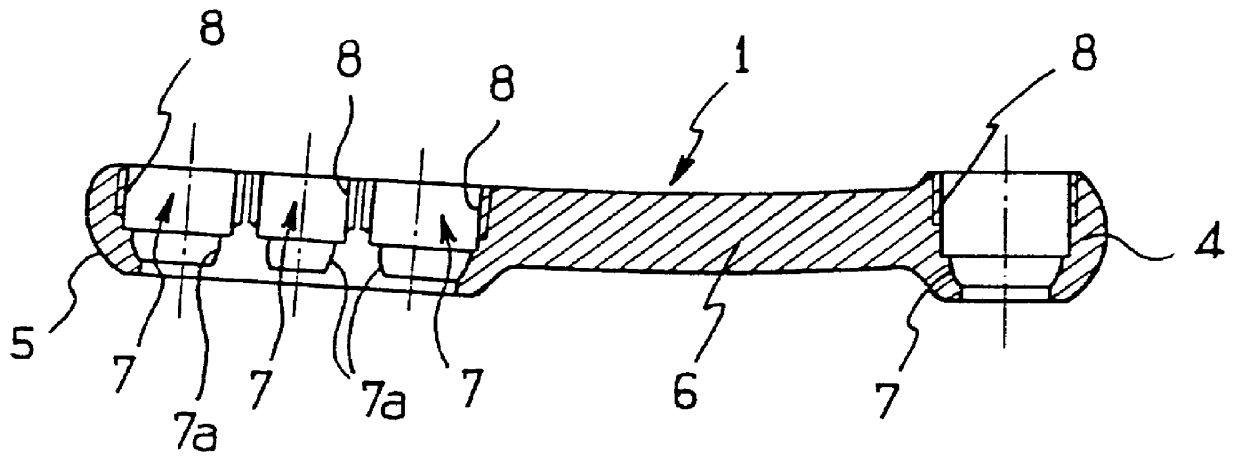
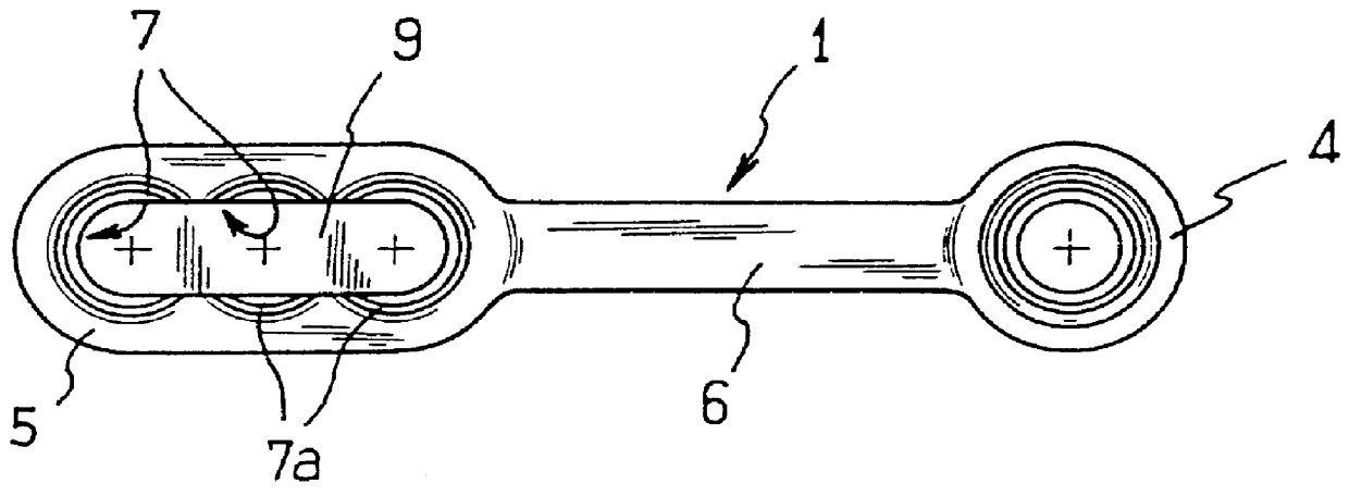
With reference now to FIGS. 1 and 2, there can be seen a sacrum-fixing element given overall reference 1 and made up of three portions: an upper eyelet 4, a sacrum plate 5, and a rod 6, e.g. a cylindrical rod, interconnection the eyelet and the plate. In profile, the overall shape of the element 1 is curved to comply with lordosis, as can be seen in FIG. 1.

A series of holes 7 is formed through the plate 5 in alignment with the long direction of the element 1 and for receiving bone-fastening screws 2.

Preferably, a range of models for the element 1 is offered to the surgeon, different models having, in particular, different lengths of rod 6, and within the plate 5, different numbers of holes for bone-fastening screws.

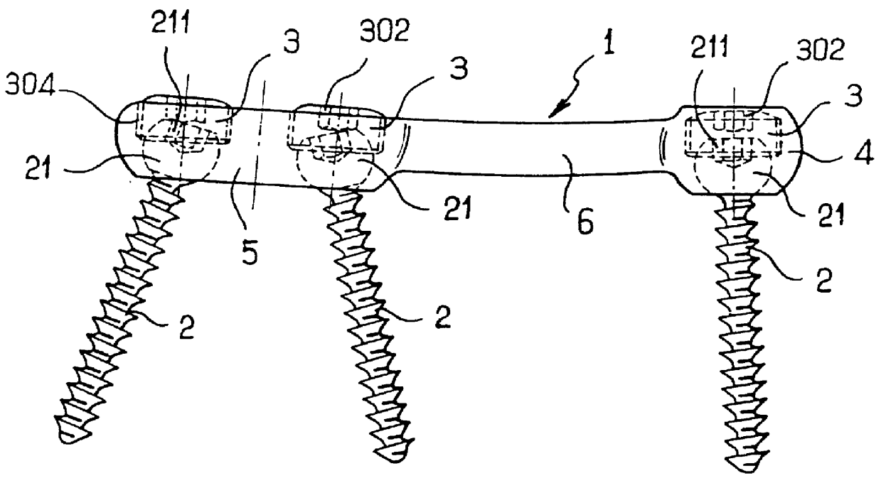
As shown in FIG. 3, in a three-h...


PUM


Abstract

A bone fixing device, in particular for fixing to the sacrum for osteosynthesis of the backbone, comprises elongate link means receiving at least one bone-fastening screw, which passes through an orifice formed in the link means. In the bottom of the link means there is included a bearing surface of essentially circular cross-section. The head of the screw includes an essentially spherical surface for bearing against said bearing surface. The link means include a first thread in the vicinity of said orifice. The device further includes a plug having a second thread suitable for co-operating with the first thread, the plug being suitable for coming into clamping contact against said screw head to hold it in a desired angular position. According to the invention, the link means are constituted by a single-piece plate-shaped element having the orifice and the first thread formed therein, and said bearing surface is essentially spherical.

Description

The present invention relates in general to a fixing device, in particular for fixing to the sacrum and usable during osteosynthesis of the backbone.It is commonplace to perform osteosynthesis of the backbone by using fixing devices that are fastened to the sacrum. This makes it possible to perform reduction movements between the various fixed stages, which movements can be contractions, distractions, or indeed reversals of vertebrae that have slipped forwards relative to the backbone, where the latter condition is known as "spondylolisthesis".Distraction is often performed for reduction of spondylolisthesis. Partial reduction is thus obtained by putting the fibers of the patient's ligament and disk apparatus back under tension. Reduction is completed by using equipment in accordance with the operating technique associated therewith. Except under exceptional circumstances, the operation is performed bilaterally. Throughout the description below, only one side of the treatment is des...

Claims


Application Information

Patent Timeline
Patent Type & Authority Patents(United States)
IPC IPC(8): A61B17/70A61B17/80A61B17/68A61B17/00A61B17/56
CPCA61B17/7059A61B17/7055A61B17/8042A61B17/8047A61B2017/00858
Inventor GANEM, FRANCK
Owner STRYKER EURO OPERATIONS HLDG LLC
Why Eureka
Try Eureka