Steady camera mount system

Inactive Publication Date: 2000-02-22
ADVANCED CAMERA SYST
View PDF13 Cites 17 Cited by
  • Summary
  • Abstract
  • Description
  • Claims
  • Application Information

AI Technical Summary

Problems solved by technology

Nevertheless new problems of stabilization are continuously being encountered as new possibilities in camera mounting are being exploited.
Also, problems inherent in conventional equipment have not been entirely overcome by recent advancements.
However this is often not straightforward as differing configurations of the camera will give different centers of mass.
This simplifies mounting but, as will be appreciated, limits applicability of the system to that of the particular camera used.
This can be problematic where creative considerations, for example, dictate use of another camera set up.
It has been recognized that this leverage can work against stability in applications such as that descri

Method used


Image

  • Steady camera mount system
  • Steady camera mount system
  • Steady camera mount system

Examples


Embodiment Construction

)

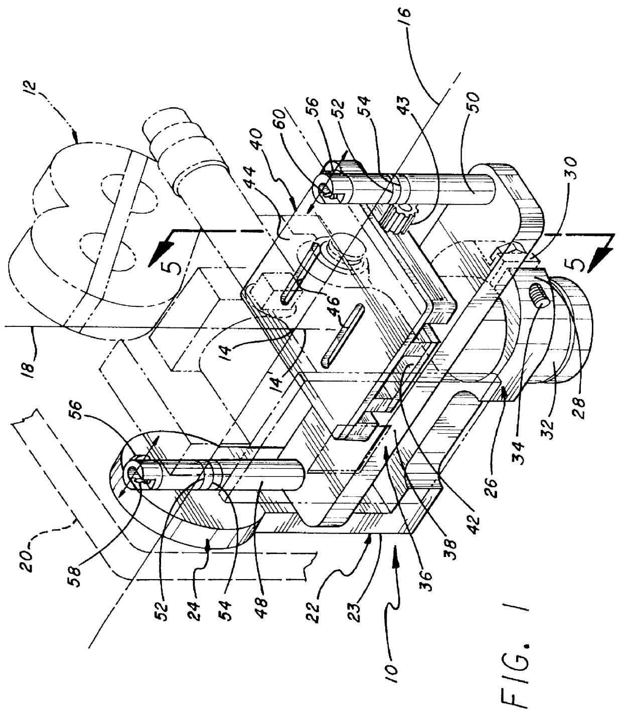
As shown in FIG. 1, a mounting system 10 for an image capture device such as a motion picture camera 12 is provided, which mitigates the effect of differential forces acting on an operator (not shown) and the system which would otherwise tend to introduce pointing error by directing such differential forces through a point 14 comprising an intersection of two orthogonal axes 16, 18 of rotation of the mounting system. The system accommodates placement of the center of mass of the mounting system components rotatable about these axes also at this point so that pointing errors due to forces induced on the system by accelerations are mitigated, being directed through this intersection point, and accordingly not inducing a tendency to rotate about either axis.

The mounting system depends from a supporting structure 20, such as a counterbalanced beam, for example, enabling the camera mounting system 10 with a camera 12 mounted to "float" and lessens or even substantially eliminates transm...


PUM


Abstract

A mounting system for minimizing pointing error in image capture equipment having a first support member rotatable about a first axis and a second support member rotatable about a second axis, the second support member including an adjustable mount allowing the image capture equipment mounted to be positioned so that the center of mass of structure rotatable about the second axis is on the second axis, and the first support member includes an adjustable positioner allowing the second support member position to be adjusted along the second axis so that the center of mass of structure rotatable about the first axis is on the first axis, and further including two hand grips carried by the second support member and positioned equidistant from the second axis of rotation and on a line passing through the second axis of rotation.

Description

1. Field of the InventionThe invention relates generally to mounting systems for photographic and other image capture equipment. More specifically, the invention relates to improved mounting systems for stabilization of such equipment in applications where the equipment and operator may be subject to forces which may cause a force differential and / or a difference of movement between the camera and the operator, such force differential tending to introduce pointing error and / or unwanted movement of the image capture equipment.2. Description of the Related ArtIn conventional mounting of image capture equipment, which herein will be understood to encompass various kinds of imaging equipment, though previously the art was directed primarily to motion picture photographic equipment for example, stabilization of the equipment is desirable. Whether applicable to photographic, video, digital image, or another form of image capture equipment, which for convenience of reference will be herein...

Claims


Application Information

Patent Timeline
IPC IPC(8): F16M11/12F16M11/04F16M11/02
CPCF16M11/04F16M11/041F16M11/12F16M13/00F16M2200/027
Inventor OFRIA, JR., RUSSELL
Owner ADVANCED CAMERA SYST
Why Eureka
Try Eureka