An adjustable hanger hinge

Active Publication Date: 2015-12-24
CENTOR PROD PTY LTD
View PDF7 Cites 7 Cited by
  • Summary
  • Abstract
  • Description
  • Claims
  • Application Information

AI Technical Summary

Benefits of technology

[0014]The present invention in directed to an adjustable hanger hinge which may at least partially overcome

Problems solved by technology

It has been found that with conventional hanger hinges, repeated opening and closing of the panels can result in rotation of the nut, and hence loss of adjustment.
However, such locking nut arrangements are not always effective.
Two spanners are usually required to adjust the height of the panels, and due to the positioning of the nuts in close proximity to the panels, damage may be caused to the panels through spanner slippage.
Moreover, the nuts are not aesthetica

Method used


Image

  • An adjustable hanger hinge
  • An adjustable hanger hinge
  • An adjustable hanger hinge

Examples


Embodiment Construction

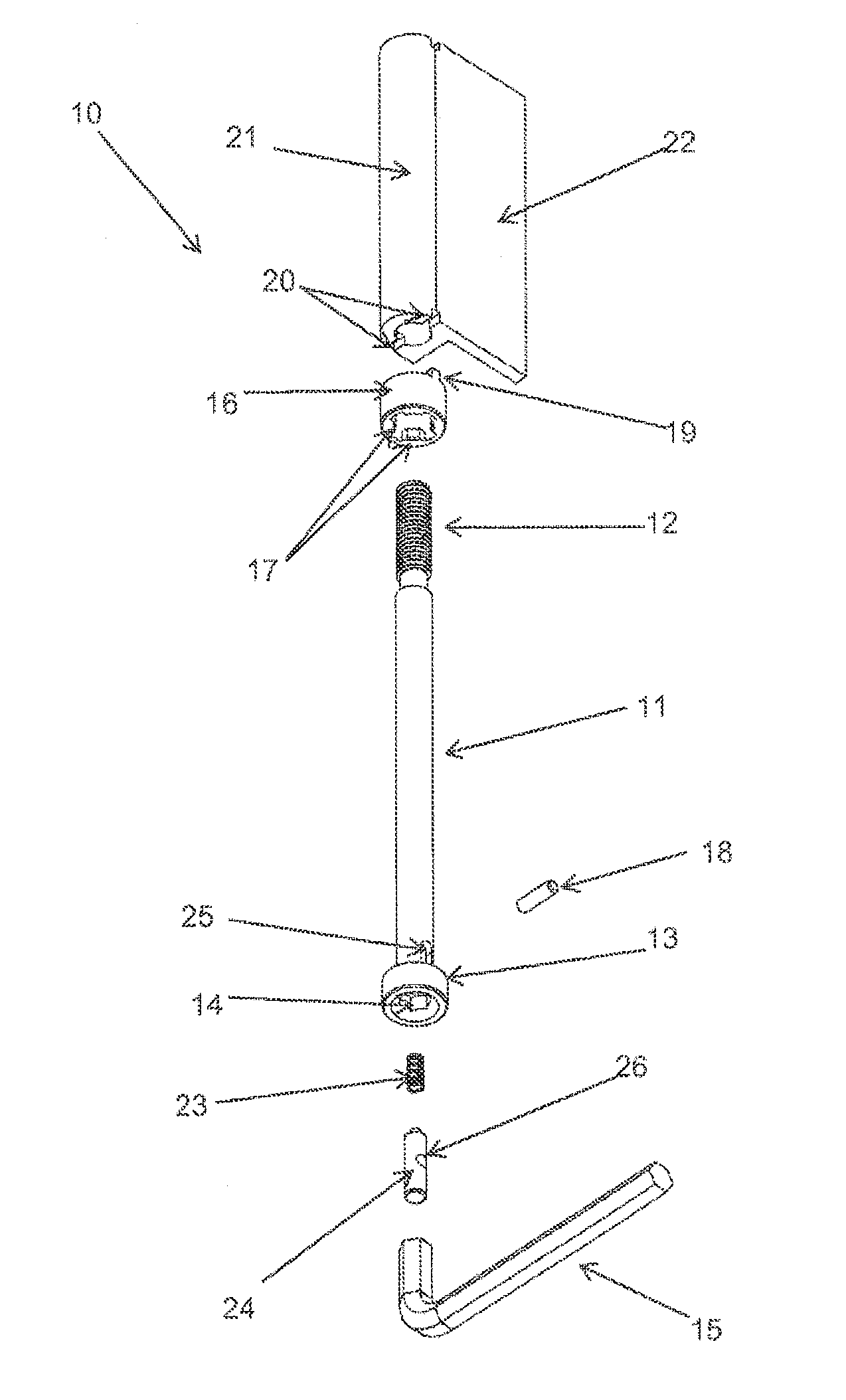
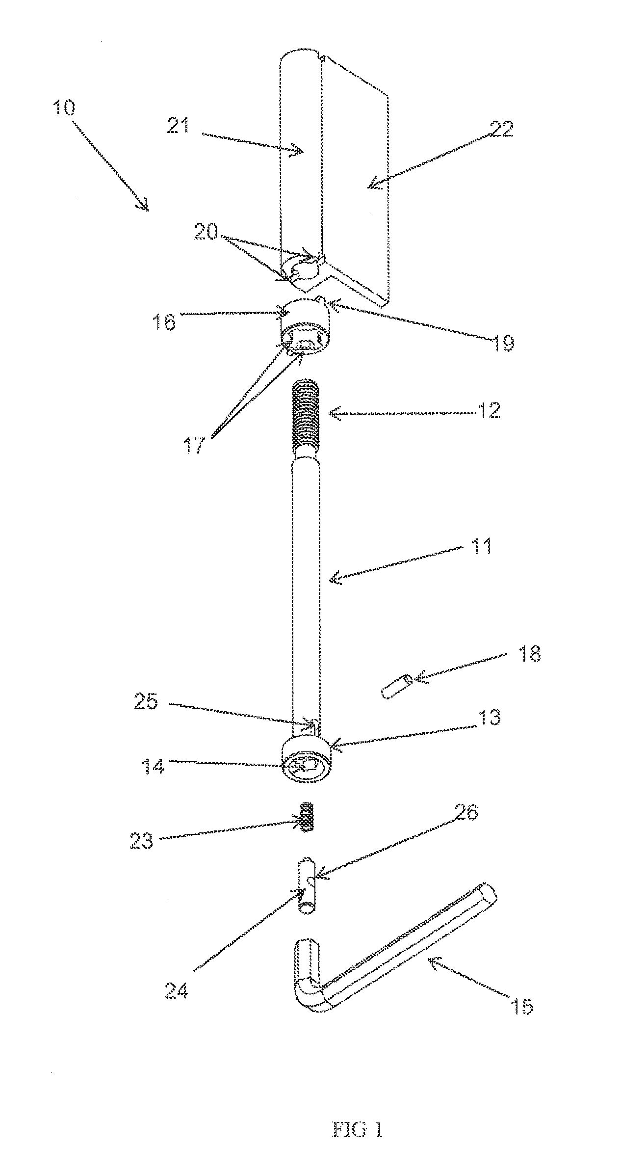
[0067]In FIG. 1 there is illustrated an exploded view of a hanger hinge 10 according to an embodiment of the present invention. The hanger hinge 10 comprises a hanger bolt 11 having a screw-threaded upper end 12 adapted for engagement with a carrier (not shown), and a lower end comprising a region of increased diameter 13 relative to the remainder of the hanger bolt 11. A receiving portion 14 is located in the underside of the hanger bolt 11, the receiving portion adapted to receive an adjusting tool in the form of an Allen key 15.

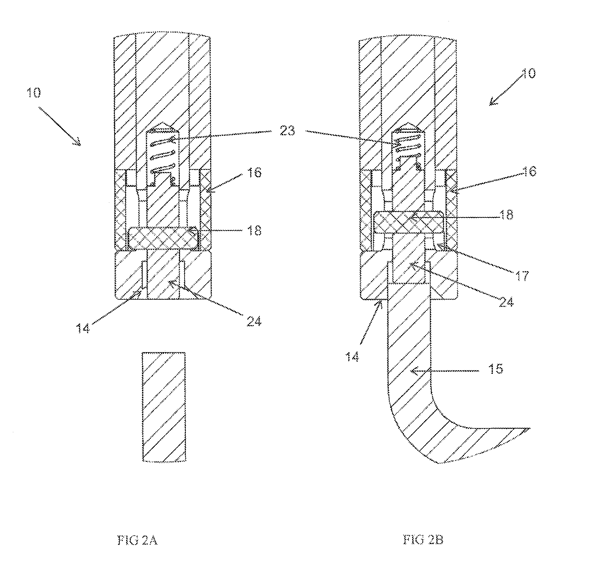
[0068]The hanger hinge 10 further comprises a sleeve 16 adapted to slide over the hanger bolt 11. The sleeve 16 is retained on the hanger bolt 11 through its abutment with the region of increased diameter 13 at the lower end of the hanger bolt 11.

[0069]The inner surface of the sleeve 16 is provided with projections 17 against which the locking member 18 abuts when the hanger hinge 10 is in the locked condition, thereby preventing rotation of the hanger bol...


PUM


Abstract

A hanger hinge for a folding door, window or similar closure having one or more panels, the hanger hinge comprising: A hanger bolt having a receiving portion in a lower end thereof adapted to receive at least a portion of an adjusting tool; A sleeve adapted to be supported on the lower end of the hanger bolt; At least one hinge leaf pivotally mounted on the hanger bolt and adapted to be fixed to a respective panel; and A locking mechanism comprising a locking member movable axially between a locked condition in which the locking member is engaged with the sleeve in a manner to substantially preclude rotation of the hanger bolt relative to the sleeve, and an unlocked condition in which the locking member is disengaged from the sleeve by axial insertion of the adjusting tool into the receiving portion, thereby freeing the hanger bolt for rotation relative to the sleeve.

Description

TECHNICAL FIELD[0001]The present invention relates to an adjustable hanger hinge. In particular, the present invention relates to an adjustable hanger hinge for a folding door, window or similar closure.BACKGROUND ART[0002]A hanger hinge is used to suspend a hinged panel, or a pair of hinged panels, from an overhead horizontal track while permitting the panels to pivot about a vertical binge axis. Typically, the panels are panels of a folding door, window or similar closure. If die hanger hinge is used to suspend the end panel of a series of panels, it normally has one hinge leaf fixed to that panel. If the hanger hinge is an intermediate hanger used to suspend a pair of adjacent panels, it has a pair of hinge leaves, each fixed to a respective one of the pair of adjacent panels.[0003]Throughout this specification, where the context permits, the term “panel” is intended to refer to a generally planar closure component of a folding door, window, shutter, screen or like closure. The i...

Claims


Application Information

Patent Timeline
IPC IPC(8): E05D11/10E05D15/26E05D3/02
CPCE05D11/1007E05D11/10Y10T16/5407E05D15/26Y10T16/540247E05D3/02F16B39/06E05D15/0639E05D7/0423E05Y2201/244E05Y2201/246E05Y2201/474E05Y2600/14F16B19/02F16B35/048F16B39/32E05D15/06
Inventor SMITH, MICHAEL
Owner CENTOR PROD PTY LTD
Why Eureka
Try Eureka