

Geared motor
a geared motor and gear drive technology, applied in the direction of gearing details, generators/motors, gearing, etc., can solve the problems of large accuracy, internal toothed gear, and the drive mechanism cannot give adequate support to the planetary gear
- Summary
- Abstract
- Description
- Claims
- Application Information
AI Technical Summary
Benefits of technology
Problems solved by technology
Method used
Image

Examples
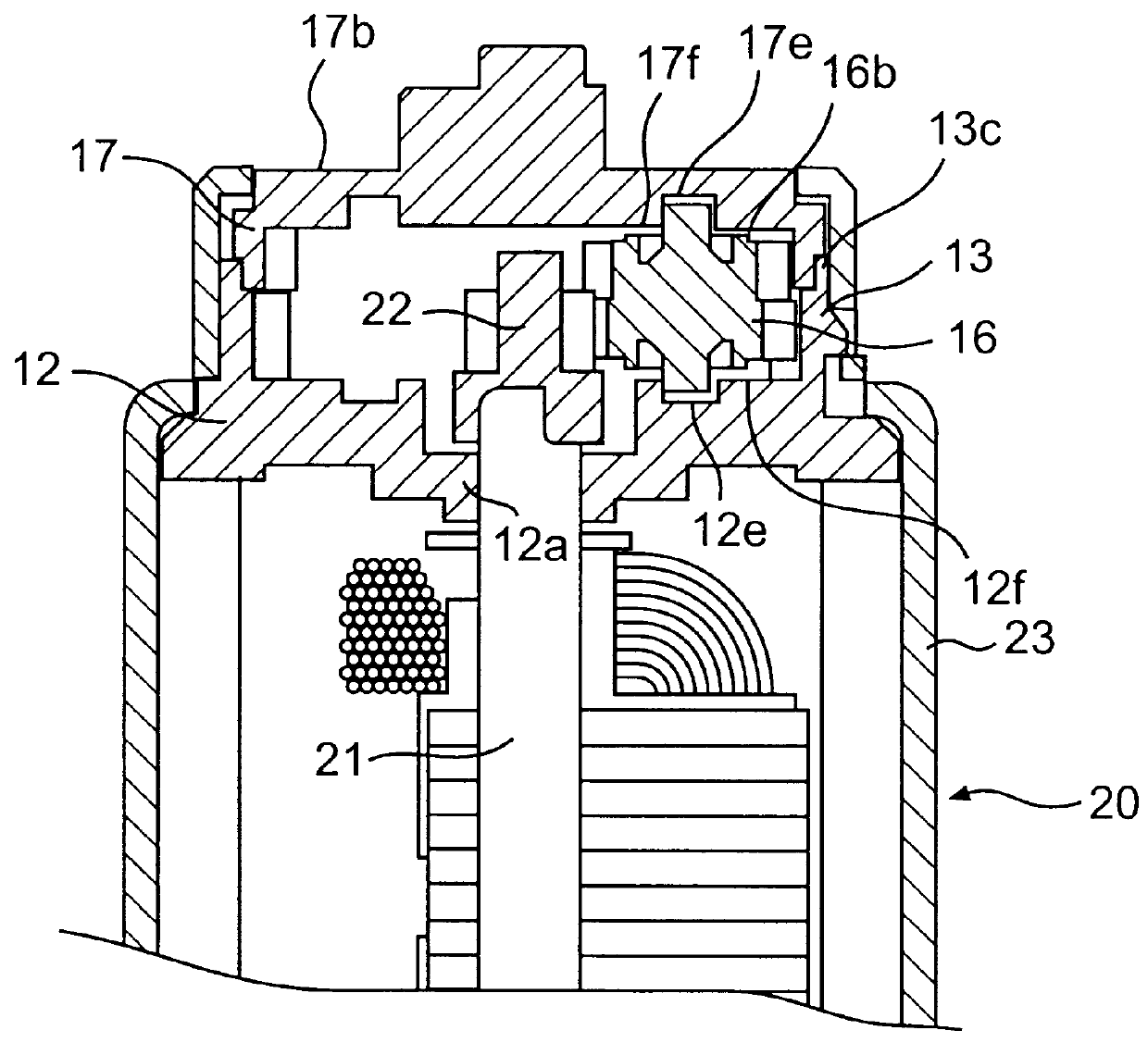
first embodiment
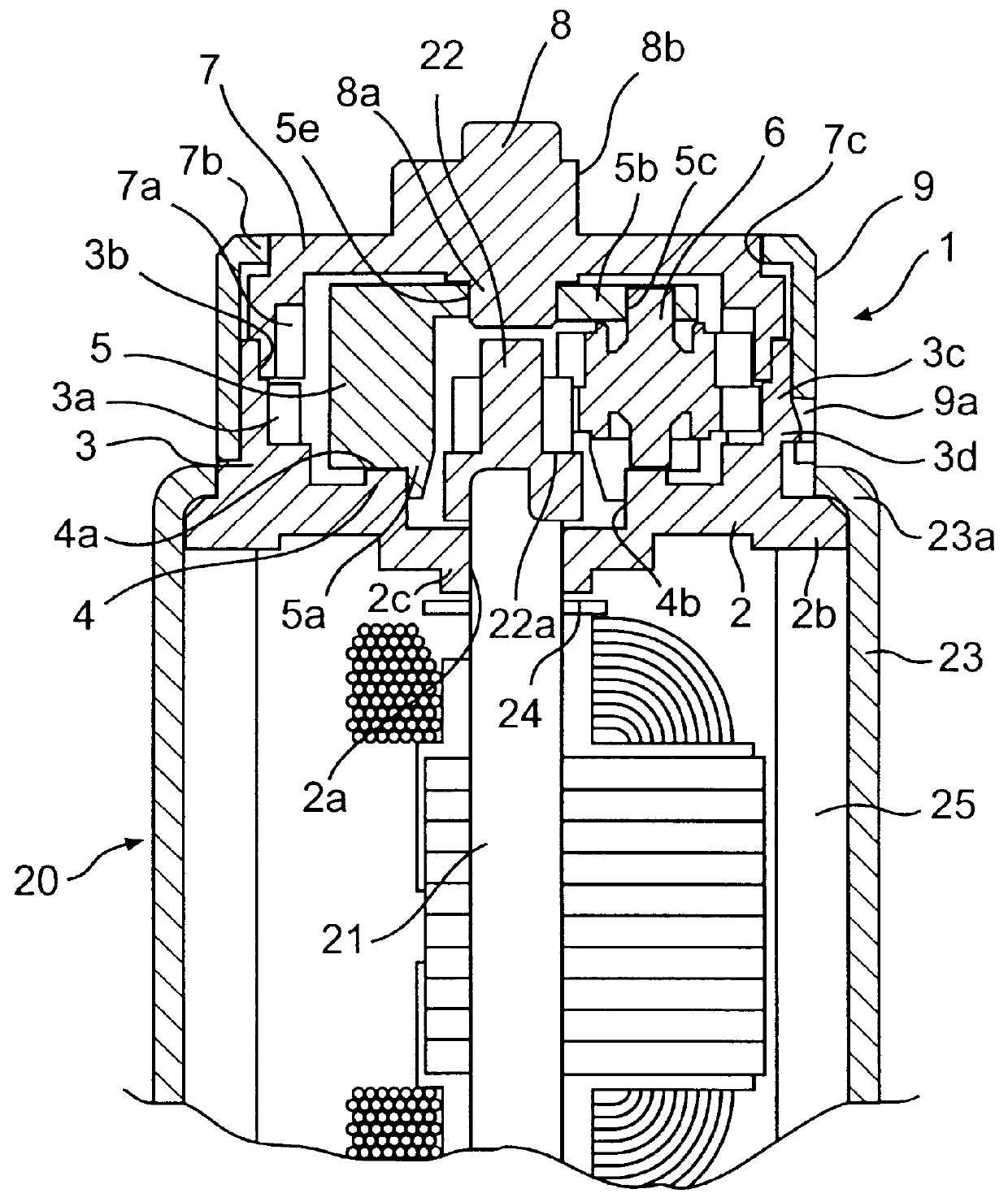
FIGS. 1 and 2 show this invention.
In the drawings, reference numeral 1 denotes a reduction unit fitted to the free end of a small motor 20. A base 2 that positions and supports the component members of the reduction unit 1 also serves as a casing to cover the free end of the small motor 20.
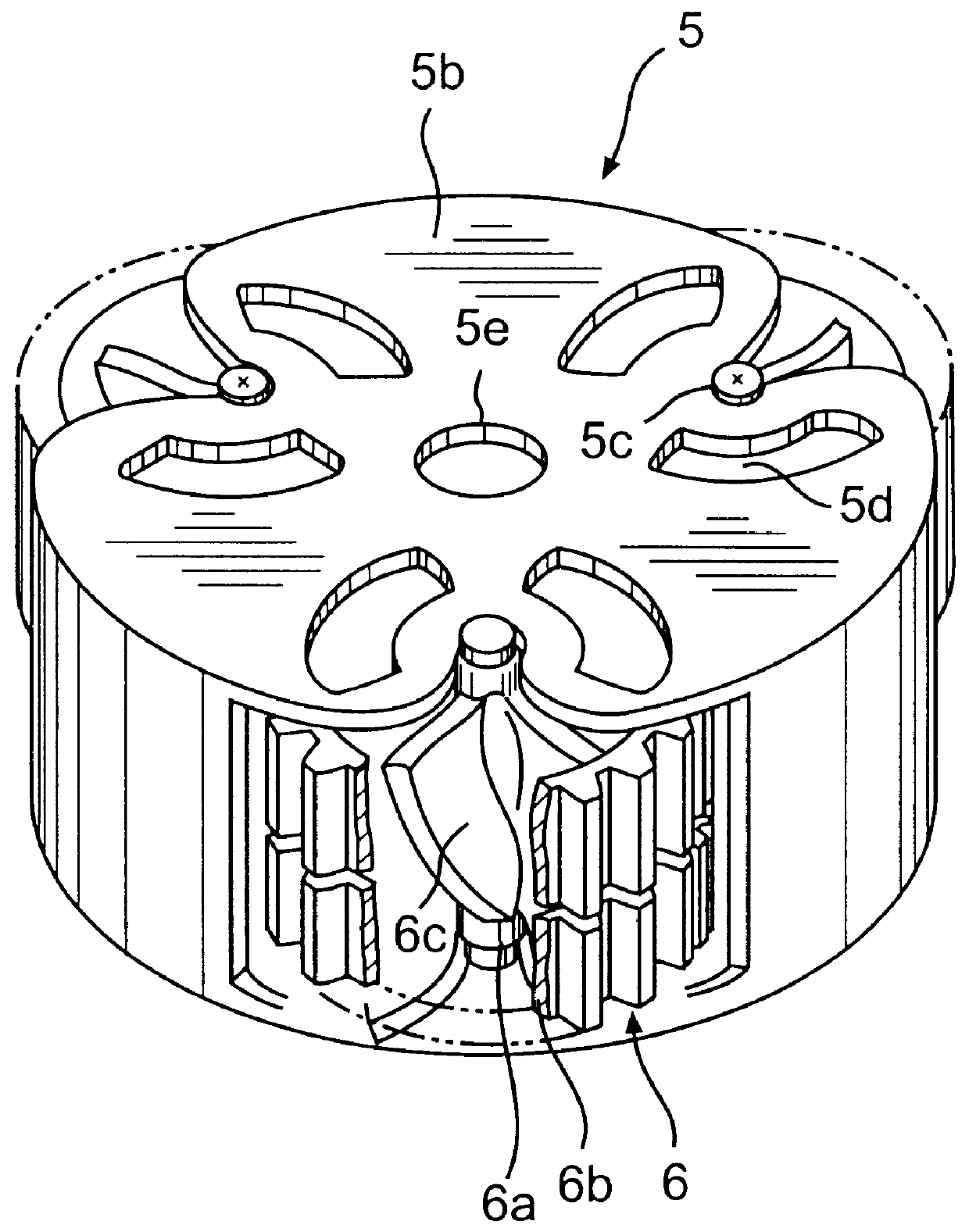
The base 2 is made of resin such as noncrystalline polyamide that permits precision forming with stationary and movable molds. On the outer side of the base 2 are formed a stationary cylindrical gear 3 having internal teeth 3a and an annular rim 4 to guide a carrier 5 that are disposed concentrically around a through hole 2a at the center to pass the rotor shaft 21.
A stepped engaging rim 2b is provided along the periphery of the base 2. The engaging rim 2b is fastened to the free end of the shaft of the small motor 20 by crimping an edge 23a of a casing 23. Or, otherwise, the engaging rim 2b is held between the edge 23a and an end of a magnet 25. Thus, the small motor 20 and reduction unit 1 are j...
PUM
 Abstract
Description
Claims
Application Information