
Data transmitting circuit and data receiving circuit between aviation equipment

A technology of aeronautical equipment and sending circuits, which is applied in the field of data sending circuits and receiving circuits between aeronautical equipment, can solve problems such as data transmission common-mode interference, achieve the effects of solving common-mode interference, high-safety transmission, and reducing verification and development costs

Active Publication Date: 2019-12-06
XIAN FLIGHT SELF CONTROL INST OF AVIC
View PDF6 Cites 0 Cited by
  • Summary
  • Abstract
  • Description
  • Claims
  • Application Information

AI Technical Summary

Problems solved by technology

[0004] The purpose of the present invention is to propose a data transmission circuit and a reception circuit between aviation equipment, the method defines a set of bus protocol, the protocol introduces isolation design in the physical layer, and solves the common mode interference problem of data transmission in specific application scenarios , at the same time, the data transmission mode and the corresponding verification method are specified in the link layer to ensure high reliability and high security data transmission

Method used


Image

  • Data transmitting circuit and data receiving circuit between aviation equipment
  • Data transmitting circuit and data receiving circuit between aviation equipment
  • Data transmitting circuit and data receiving circuit between aviation equipment

Examples


Embodiment Construction

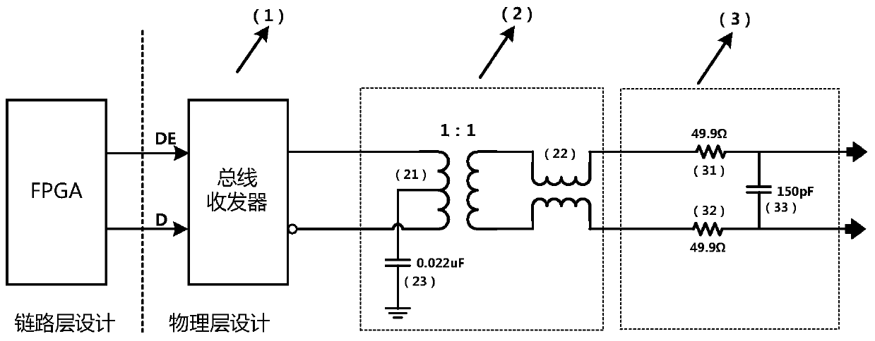
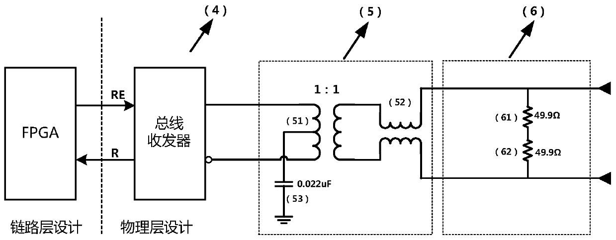
[0039] A data sending circuit and a receiving circuit between aviation equipment, the defined bus protocol includes a physical layer and a link layer. The bus protocol adopts a highly integrated design implementation scheme, with FPGA and bus transceiver as the hardware architecture, the bus transceiver and related circuits realize the physical layer, complete the conversion of bus logic signals and level signals, and implement the agreement by FPGA The link layer completes the process of grouping and unpacking data packets.

[0040] Physical layer: It mainly realizes the conversion of bus logic signal and RS485 standard level signal. The realization of the physical layer includes: level conversion design, isolation design, and impedance matching design, in which the level conversion design is implemented using RS485 transceivers; the isolation design uses transformers to isolate the bus transceiver signal from the cable signal to improve the bus interface. Excellent anti-com...


PUM


Abstract

The invention provides a data transmitting circuit between aviation equipment. The circuit comprises a level conversion circuit, an isolation circuit and an impedance matching circuit; one end of thelevel conversion circuit is connected with an FPGA, the other end of the level conversion circuit is connected with the isolation circuit, and the level conversion circuit is used for receiving a buslogic signal sent by the FPGA and converting the bus logic signal into a standard level signal; one end of the isolation circuit is connected with the level conversion circuit, the other end of the isolation circuit is connected with the impedance matching circuit, and the isolation circuit is used for isolating the standard level signal from a cable bus signal output by the impedance matching circuit; one end of the impedance matching circuit is connected with the isolation circuit, the other end of the impedance matching circuit is connected with external aviation equipment, and the impedance matching circuit is used for outputting cable bus signals and achieving impedance matching of the data sending circuit between the aviation equipment.

Description

technical field [0001] The invention belongs to the technical field of communication, and in particular relates to a data sending circuit and a receiving circuit between aviation equipment. Background technique [0002] During the working process of the aircraft, there is frequent data and command interaction between aviation equipment. Take the flight control computer and actuator control electronics as an example. During the entire aircraft working process, the actuator control electronics receives and processes the control stick, Signals such as steering wheel, pedals, air data, attitude information, flap position, and heading damping are sent to the flight control computer through the bus. After receiving the data, the flight control computer performs control law calculation based on these data , and send the calculated rudder surface control command to the actuator control electronics through the bus, so as to realize the control of the aircraft rudder surface. If ther...

Claims


Application Information

Patent Timeline
IPC IPC(8): H04L29/06H04B1/04H04B1/16
CPCH04B1/04H04B1/16H04L69/03H04L69/26
Inventor 张鹏飞张兴隆刘坤刘振荣杨光
Owner XIAN FLIGHT SELF CONTROL INST OF AVIC
Learn More