Vector map planarization and trapping

a vector map and vector technology, applied in the direction of image enhancement, instruments, static indicating devices, etc., can solve the problems of small gap between regions of different colors, difficult control of separation, and inability to achieve color printing

Inactive Publication Date: 2000-02-29
ADOBE INC
View PDF3 Cites 54 Cited by
  • Summary
  • Abstract
  • Description
  • Claims
  • Application Information

AI Technical Summary

Problems solved by technology

High-quality printing, such as that required by the publishing industry, poses many difficult problems in controlling the separations.
For example, color printing is compromised if paper is not properly aligned as the paper makes multiple passes through the plates of a printer.
As a result, the several inks are never perfectly aligned with one another, and a small gap between regions of different colors may occur, which is often quite visible to the eye as an off-color line.
However, trapping capabilities in originating programs have typically been very limited.
Thus, the trap results in these instances are less than desirable.
Furthermore, because trap parameters (e.g., overlap width) are specific to the characteristics of each printing press, these values are typically not available at the time a document is created, and requirin

Method used


Image

  • Vector map planarization and trapping
  • Vector map planarization and trapping
  • Vector map planarization and trapping

Examples


Embodiment Construction

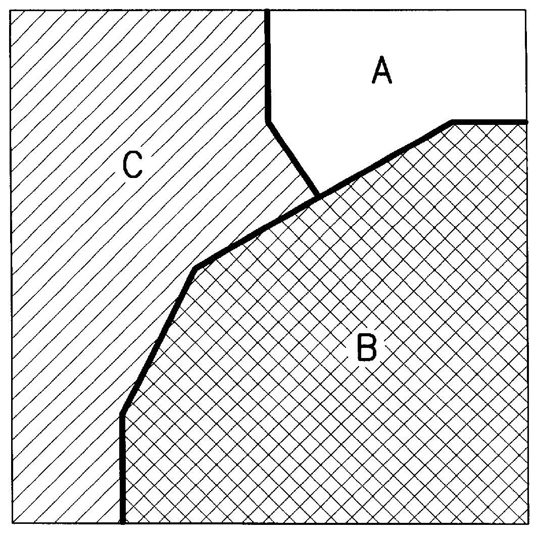
An example of vector map trapping for part of a page comprising two objects on a background object is shown in FIGS. 1-5. More specifically, FIG. 1 is a diagram of part of two polygon objects A, B on a tile with background object C (a background object can either be the page or an object that entirely covers the tile). FIG. 1 shows how the objects would print, with object B overprinted on object A, and both objects A, B printing on top of object C.

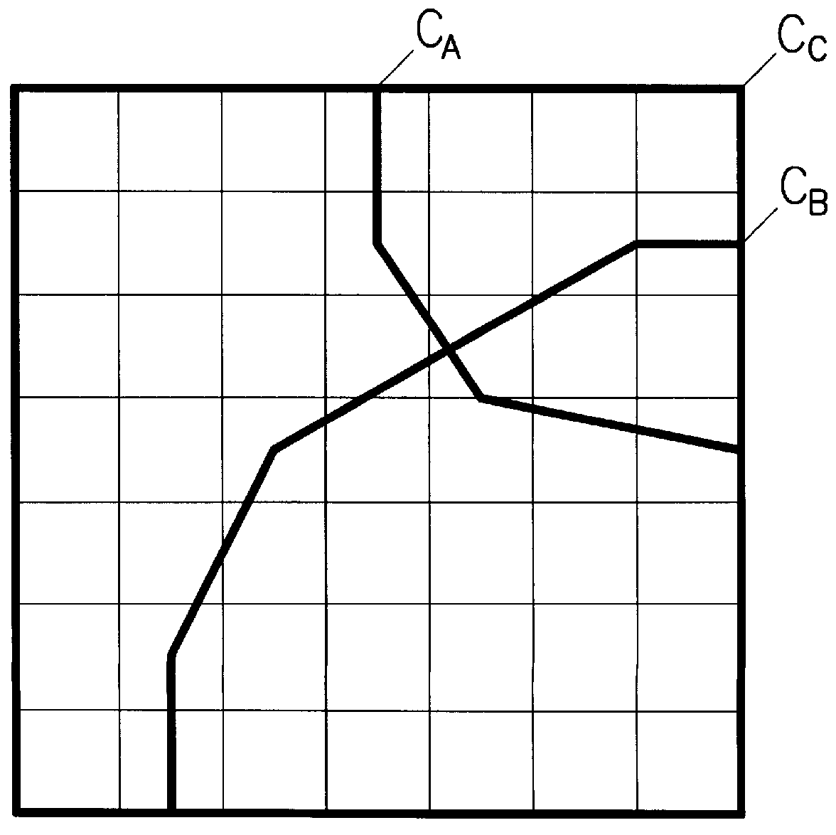
FIG. 2 is a diagram of polygon contour segments C.sub.A, C.sub.B, comprising edges of the two objects A, B, drawn on an arbitrary 7.times.7 vector map grid superimposed on the tile of FIG. 1. The background object C is represented by the vector map boundary C.sub.C.

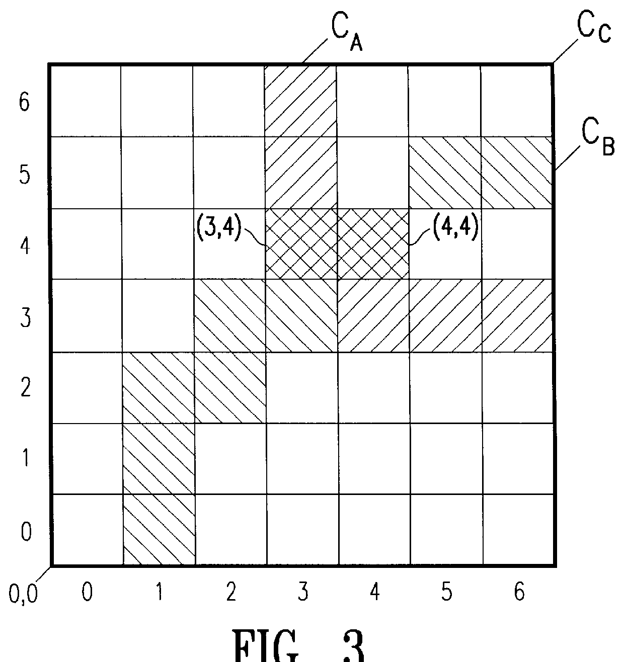
FIG. 3 is a diagram of a vector map representation of the tile of FIG. 2. The polygon contour segments C.sub.A, C.sub.B are shown visually represented in the vector map as hatched cells. In the preferred embodiment, a pointer to each edge segment from each contour segment C.sub....


PUM


Abstract

A vector map representation of page information to perform trapping. The vector map representation combines the positive attributes of both raster and vector based representations to make trapping more efficient by combining the sparseness of the vector representation and the constant unit complexity of the raster representation. In the preferred embodiment of the invention, a page is defined by tiles, and each tile is mapped to a 2-D array of edge pointers referred to as the vector map. Each cell in the vector map contains a list of all of the edges of the image that pass through it. A pair of edges can only interact if they are in the same vector map cell list. Thus, edge intersection and color finding tests are localized as with raster based trapping while the data sparseness of vector based trapping is retained. For a suitably chosen vector map size, a single edge generally does not intersect many cells. A trapping function is applied to edges as determined from the vector map.

Description

1. Field of the InventionThis invention relates to planarizing a set of overlapping objects, and more particularly to color trapping in electronic printing systems.2. Description of Related ArtFor many years, the preferred process for color printing on paper has been to process the page in multiple exposures, or separations. Each separation exposes selected areas of the paper to an ink of a different color. The usual process ink colors are cyan, magenta, yellow and "key" (CMYK), where key is usually black. Additional color inks are often used as spot colors in additional separations.High-quality printing, such as that required by the publishing industry, poses many difficult problems in controlling the separations. For example, color printing is compromised if paper is not properly aligned as the paper makes multiple passes through the plates of a printer. As a result, the several inks are never perfectly aligned with one another, and a small gap between regions of different colors ...

Claims


Application Information

Patent Timeline
IPC IPC(8): G06T5/00B41J2/525B41J5/30G06T9/20H04N1/46H04N1/58H04N1/60
CPCG06T7/0083H04N1/58G06T7/12
Inventor YHANN, STEPHAN
Owner ADOBE INC
Why Eureka
Try Eureka