Dector system for access control, and a detector assembly for implementing such a system

a detector and access control technology, applied in the direction of magnetic measurement, geological measurement, reradiation, etc., can solve the problems of high cost of a transponder with an in-built battery, very harmful detection operations for such people, and industrial developmen

Inactive Publication Date: 2000-03-14
ALESSANDRO MANNESCHI
View PDF3 Cites 64 Cited by
  • Summary
  • Abstract
  • Description
  • Claims
  • Application Information

AI Technical Summary

Benefits of technology

Nevertheless, an object of the present invention is now to provide novel means enabling a metal detector and a transponder detector to be combined, while avoiding the drawbacks of previously known dispositions.

Problems solved by technology

Such detectable operations can be very harmful to the security of such people who are thus identified as being unusual.
Nevertheless, the means described in document U.S. Pat. No. 5,523,739 have yet to be developed industrially on the large scale expected from the marked advantages that such means offer compared with the state of the art.
Another problem is the cost of a transponder with an in-built battery, and this factor limits commercialization to applications where large numbers of transponders are required.
Another negative factor of battery transponders is their limited lifetime which makes the apparatus unusable after being active for a certain length of time.
The problems encountered in this way have not yet been solved in satisfactory manner, since any modification of the system relative to the means described in document U.S. Pat No. 5,523,739 fails because of the incompatibilities of principle that exist between metal detectors and hands-free transponder detectors, as recalled above.

Method used


Image

  • Dector system for access control, and a detector assembly for implementing such a system
  • Dector system for access control, and a detector assembly for implementing such a system
  • Dector system for access control, and a detector assembly for implementing such a system

Examples


Embodiment Construction

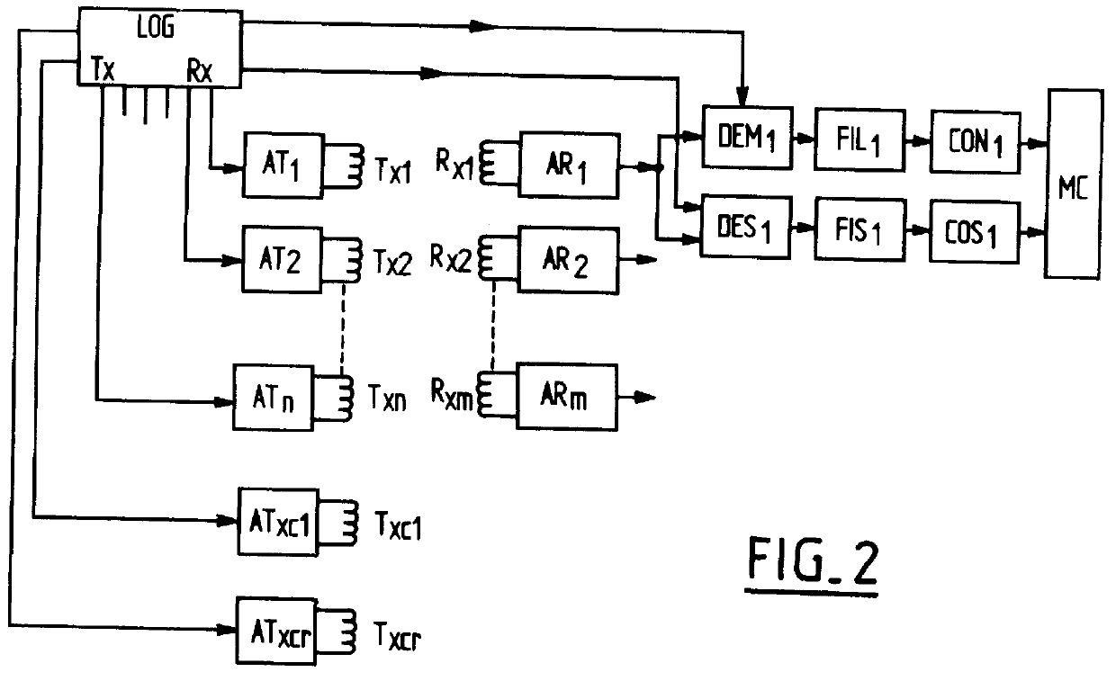
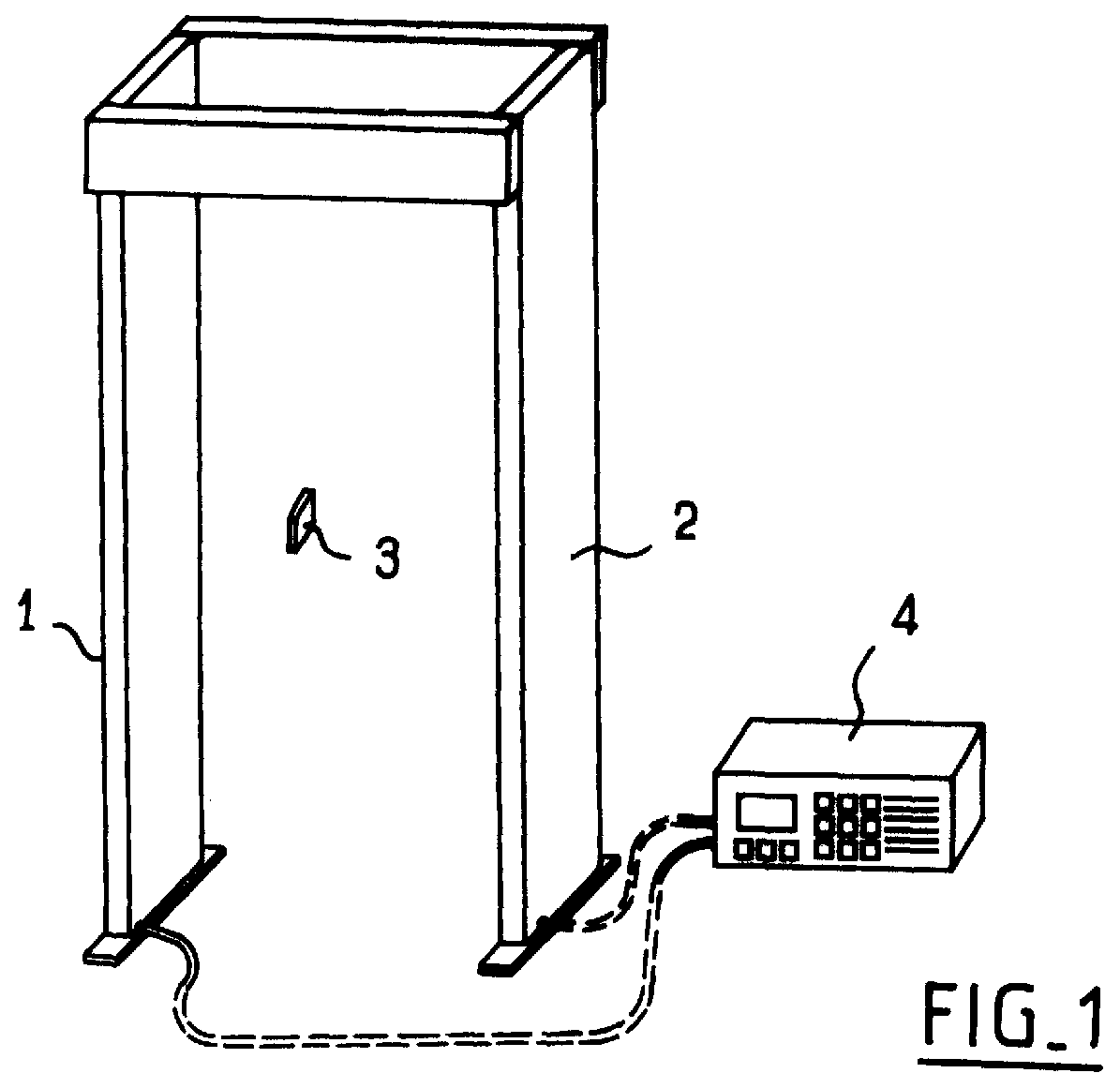
The general structure of a detector system of the present invention is substantially as shown in accompanying FIG. 1.

Thus, the system of the present invention mainly comprises:

transmitter coils 1 suitable for generating magnetic fields;

associated receiver coils 2;

transponders 3; and

processor circuits 4.

As mentioned above, in the context of the present invention, the transmitter coils 1 are adapted to generate respective frequencies Fxi and Fxci, Fxi for exciting and detecting any weapons passing between the transmitter coils 1 and the receiver coils 2, and secondly Fxci for activating the transponders 3.

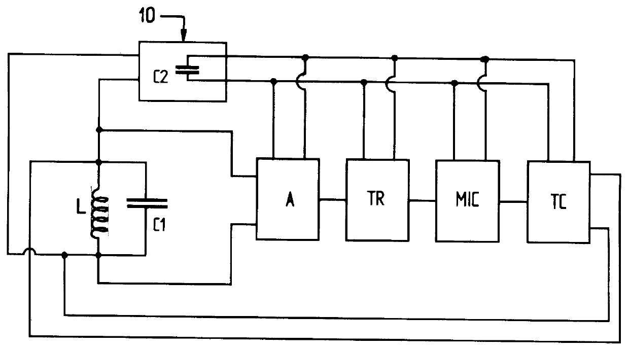
In addition, the transponders 3 are adapted to generate an identifiable signature, preferably a determined code that modulates a transmission.

In the context of the invention, the transponders 3 have means 10 suitable for electrically powering their internal circuits from the signal received at the "activation" frequency Fxci.

In addition, each weapon excitation and detection frequency...


PUM


Abstract

The present invention provides a detector system for access control, the system comprising: transmitter coils; associated receiver coils; transponders suitable for generating identifiable signatures; and processor circuits adapted firstly to detect a weapon passing between the transmitter and receiver coils by analyzing variations in the signal received by the receiver coil, and secondly to detect the identifiable signature of a transponder on the basis of the signal received by the receiver coils; wherein: the transmitter coils are adapted to generate respective frequencies, firstly for exciting and detecting any weapons passing between the transmitter and receiver coils, and secondly for activating transponders; the transponders have means suitable for powering their internal circuits electrically from the signal received at the "activation" frequency; each weapon excitation and detection frequency is very different from each frequency used for activating transponders and for transponder signatures; and the signals used for detecting transponders are taken from the outputs of receiver coils that are also used for detecting weapons.

Description

The present invention relates to the field of access control devices.Applications for the present invention can be found in controlling access at the entrance to numerous sites, such as and without any limitation: banks, embassies, military installations, airports, etc.More precisely, the present invention relates to a device which combines a metal detector in order to detect any weapons, and a transponder detector in order to detect and optionally authorize passage of authorized persons in spite of a weapon being detected.In this respect, the present invention provides improvements to the means described in documents U.S. Pat. No. 5,523,739.Metal detectors and transponder detectors have already given rise to abundant literature.It is known that most metal detectors comprise transmitter coils, receiver coils, and an electronic processor circuit adapted to detect variations in the signals received by the receiving coils relative to a reference value.Still more precisely, present-day ...

Claims


Application Information

Patent Timeline
Patent Type & Authority Patents(United States)
IPC IPC(8): G01V3/10
CPCG01V3/105
Inventor ALESSANDRO, MANNESCHI
Owner ALESSANDRO MANNESCHI
Why Eureka
Try Eureka