Automatic transmission power control circuit

a transmission power and control circuit technology, applied in the direction of electrically long antennas, antennas, electrical equipment, etc., can solve the problems of transmission power not being increased to the desired power level, distortion of transmission wave output, and alarm signal generation

Inactive Publication Date: 2000-03-14
FUJITSU LTD
View PDF10 Cites 65 Cited by
  • Summary
  • Abstract
  • Description
  • Claims
  • Application Information

AI Technical Summary

Problems solved by technology

Additionally, an alarm signal may be generated when an abnormality occurs in a transmission power, that is, when the transmission power is out of an allowable range.
However, when a malfunction occurs in a transmission circuit of the power amplifier 2, the transmission power may not be increased to the desired power level even when the magnitude of amplification of the variable gain amplifier 1 is continuously increased by increasing the output of the up-down counter 7.
As a result, a distortion may occur in the transmission wave output from the antenna ANT, an adjacent channel leakage power may be increased, or a modulation accuracy ma

Method used


Image

  • Automatic transmission power control circuit
  • Automatic transmission power control circuit
  • Automatic transmission power control circuit

Examples


first embodiment

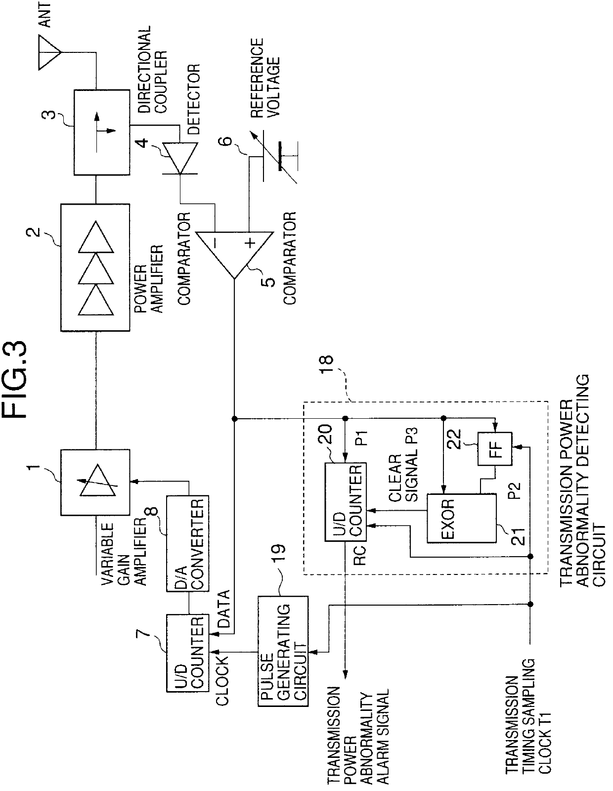
In the first embodiment, a transmission power abnormality detecting circuit 18 is provided so as to cumulate the output of the comparator 5. The transmission power abnormality detecting circuit 18 includes an up-down counter 20 which is separate from the up-down counter 7, a flip-flop circuit (FF) 22 and an exclusive OR circuit (EXOR) 21. A transmission timing sampling clock signal T1 is provided to the up-down counter 20 and the flip-flop circuit 22. The flip-flop circuit 22 and the exclusive OR circuit 21 together serve to detect an inversion of the output of the comparator 5. An output P2 of the flip-flop circuit 22 is input to the exclusive OR circuit 21. The up-down counter 20 is reset by an output (clear signal P3) of the exclusive OR circuit 21.

In the first embodiment, the output of the comparator 5 is cumulated by the up-down counter 20 at a timing determined by the transmission timing sampling clock T1. Additionally, the output of the comparator 5 is supplied to the exclusi...

second embodiment

FIG. 5 is a circuit diagram of a variation of the automatic transmission power control circuit according to the present invention. In FIG. 5, parts that are the same as the parts shown in FIG. 4 are given the same reference numerals, and descriptions thereof will be omitted.

The automatic transmission power control circuit shown in FIG. 5 has the same structure as that of the automatic transmission power control circuit according to the second embodiment shown in FIG. 4 except for the up-down counter 7 being used for providing the count value of the output of the comparator 5 to the transmission power abnormality detecting circuit 23. That is, the up-down counter 7 also serves a function of the up-down counter 50. This provides a simple structure to the transmission power abnormality detecting circuit 23.

A description will now be given, with reference to FIG. 6, of a third embodiment of the present invention. FIG. 6 is a circuit diagram of an automatic transmission power control circ...

third embodiment

FIG. 7 is a circuit diagram of a variation of the automatic transmission power control circuit according to the present invention. In FIG. 7, parts that are the same as the parts shown in FIG. 6 are given the same reference numerals, and descriptions thereof will be omitted.

The automatic transmission power control circuit shown in FIG. 7 has the same structure as that of the automatic transmission power control circuit according to the third embodiment shown in FIG. 6 except for the up-down counter 7 being used for providing the count value of the output of the comparator 5 to the transmission power abnormality detecting circuit 29. That is, the up-down counter 7 also serves a function of the up-down counter 51. This provides a simple structure to the transmission power abnormality detecting circuit 29.

FIG. 8 is a block diagram of the pulse generating circuit 19 shown in FIGS.3 to 7.

In the pulse generating circuit 19, an output of an oscillator 33 is supplied to an OR circuit 39 via...


PUM


Abstract

An automatic transmission power control circuit which can detect an abnormality in a transmission power without a comparing circuit which compares a detected voltage with reference voltages. A detector detects a voltage corresponding to the transmission power and outputs a detected voltage. A comparator compares the detected voltage with a reference voltage so that the transmission power is controlled based on an output of the comparator. A transmission power abnormality detecting circuit includes a counter which cumulates the output of the comparator. The transmission power abnormality detecting circuit outputs a transmission power abnormality detection signal when an output of the counter is a value which is out of a normal range when the automatic power transmission control circuit is normally functioning.

Description

1. Field of the InventionThe present invention relates to an automatic transmission power control circuit provided with a function to detect an abnormality of a transmission power and, more particularly, to an automatic transmission power control circuit for a transmitter which requires a monitor of the transmission power in a base station of a mobile radio communication system.2. Description of the Related ArtAn allowable fluctuation of an output power of a base station in a mobile communication system is specified, for example, as a range from +20 to -50% with respect to a reference transmission power. In this case, an automatic transmission power control circuit is provided in the base station in order to absorb fluctuation in the transmission power due to allowable tolerances of circuitry and a change in circumstances. Additionally, an alarm signal may be generated when an abnormality occurs in a transmission power, that is, when the transmission power is out of an allowable ran...

Claims


Application Information

Patent Timeline
IPC IPC(8): H01Q3/26H03G3/30H04B1/04
CPCH01Q3/2605H03G3/3042H03G3/3047
Inventor ONODA, MASAHIRO
Owner FUJITSU LTD
Why Eureka
Try Eureka