Compact potentiometer

a potentiometer and compact technology, applied in the field of position sensors, can solve the problems of large potentiometer sensors, difficult to fit into cramped spaces, and inconvenient use,

Inactive Publication Date: 2000-03-21
CTS CORP ELKHART
View PDF13 Cites 26 Cited by
  • Summary
  • Abstract
  • Description
  • Claims
  • Application Information

AI Technical Summary

Problems solved by technology

Potentiometer sensors such as those described above suffer from several drawbacks.
In particular, pedal position or throttle sensors in automobiles need redundancy: if only one potentiometer is used and this sensor fails, a potentially dangerous situation may result.
Thus, without a way to make potentiometers smaller while retaining high resolution and possibly redundancy, potentiometer sensors will be larger than ideal and will be hard to fit into cramped spaces.

Method used


Image

  • Compact potentiometer

Examples


Embodiment Construction

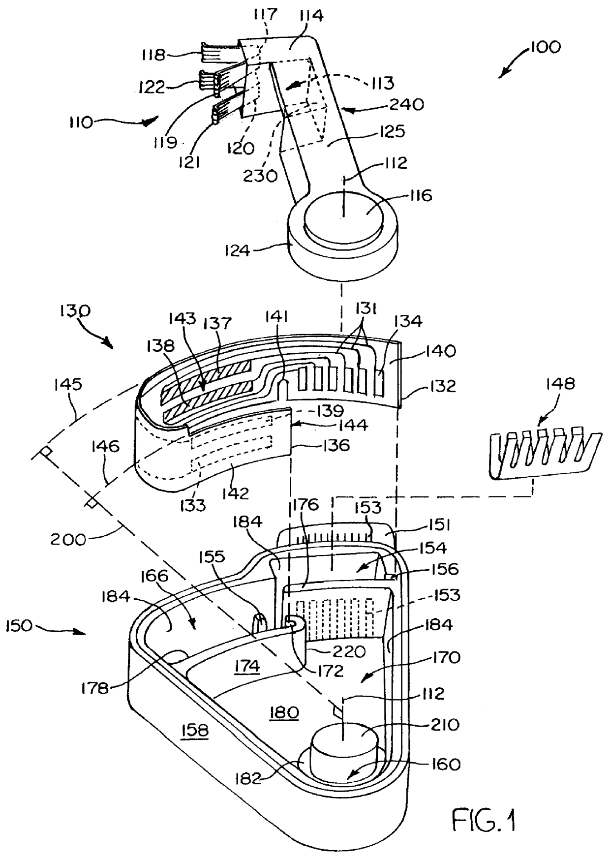
According to the present invention, a sensor is disclosed that fits in a compact package. This compact sensor is ideal for sensing rotary positions and for accommodating one or more potentiometers. The resistor track is parallel and opposed to the collector track, and the wiper is placed between the two tracks to swipe both of them in one embodiment. This allows a short package, because the tracks are opposed to each other rather than being in a line, and a narrow package, because the tracks are not placed side by side. Another advantage of the invention is that putting the resistor track on a larger radius and the collector track on a smaller radius allows the resistor track to be longer. Having a longer resistor track allows a higher resolution, yet a package containing the potentiometer will still be relatively small.

In a second embodiment, two or more potentiometers are mounted so that the resistor tracks are next to and parallel to each other. The collector tracks are also next...


PUM


Abstract

A sensor is disclosed that fits in a compact package. This compact sensor is ideal for sensing rotary positions and for accommodating one or more potentiometers. The resistor track is parallel and opposed to the collector track, and the wiper is placed between the two tracks to swipe both of them in one embodiment. This allows a short package, because the tracks are opposed to each other rather than being in a line, and a narrow package, because the tracks are not placed side by side. Another advantage of the invention is that putting the resistor track on a larger radius and the collector track on a smaller radius allows the resistor track to be longer. Having a longer resistor track allows a higher resolution, yet a package containing the potentiometer will still be relatively small. Several potentiometers may be placed in the sensor to provide redundancy yet retain compactness.

Description

1. Technical FieldsThis invention generally relates to position sensors and more specifically relates to a high resolution potentiometer placed in a small package.2. Background ArtPosition sensors are widely used in a number of industries to measure the position of various mechanical devices. In particular, position sensors are used in the automobile industry for this purpose. For instance, the position of a driver's seat may be measured and recorded to be recalled later; this allows two or more people to store individual seat positions. As another example, the position of the accelerator pedal may be taken and this position used for various purposes, such as adjusting the throttle. These types of positions can be determined by sensing the angular rotation of a rotor. The farther in angular position the rotor has rotated, the greater the seat inclination or declination, or the faster or slower the driver wishes to go.Many of these rotary position sensors are made from potentiometers...

Claims


Application Information

Patent Timeline
Patent Type & Authority Patents(United States)
IPC IPC(8): H01C10/30H01C10/00
CPCB60N2/04H01C10/34B60R16/037B60N2002/0272B60N2/0272
Inventor KAIJALA, MURRAY
Owner CTS CORP ELKHART
Why Eureka
Try Eureka