Bar clamp for wood manufacturing

a technology for clamping devices and woodworking, applied in the direction of clamps, manufacturing tools, and surfaces, to achieve the effect of light weight and ease of handling

Inactive Publication Date: 2000-04-18
DE SOUZA STEPHEN
View PDF7 Cites 46 Cited by
  • Summary
  • Abstract
  • Description
  • Claims
  • Application Information

AI Technical Summary

Benefits of technology

An object of the present invention is to provide a bar clamp made of light metal, namely, aluminum, which makes them lightweight and easier to handle as opposed to existing bar clamps which usually are of heavy metal which makes them heavy weight.
Another advantage of the new bar clamp of the present invention is a measurement gauge built onto the bar. The measurements are in inches (measurements could also be in centimeters) each 1" apart (or 1 cm apart) and each clamp has the measurement gauge according to the length of each bar clamp. The measurement gauge is calculated between the tightening attachment pieces. Moreover, at each 1" point of measurement, a hole is located on the bar and on the movable tightening attachment through which a metal pin is inserted to hold the movable tightening attachment piece in the desired measurement location. Existing bar clamps not having a measurement gauge, will necessitate adjusting each individual clamp onto the workpiece itself before tightening. However, with the new designed bar clamp, the clamp can be set to the measurement desired, using the measurement gauge, prior to fitting and tightening onto the workpiece.
Another advantage of the present invention is that it is constructed of two straight bars, approximately 11 / 2" apart, held by brace pieces. This feature allows the clamp to be used "upside down" for clamping without "falling over." Existing bar clamps have only a single bar and for this method of clamping, since existing bar clamps have only a single bar, a wooden block with a groove is used to support the clamp in an "upside down" position, otherwise it will "fall over."

Problems solved by technology

Furthermore, existing bar clamps are constructed with fixed non-movable tightening attachments limiting their usage to specific applications.

Method used


Image

  • Bar clamp for wood manufacturing
  • Bar clamp for wood manufacturing
  • Bar clamp for wood manufacturing

Examples


Embodiment Construction

)

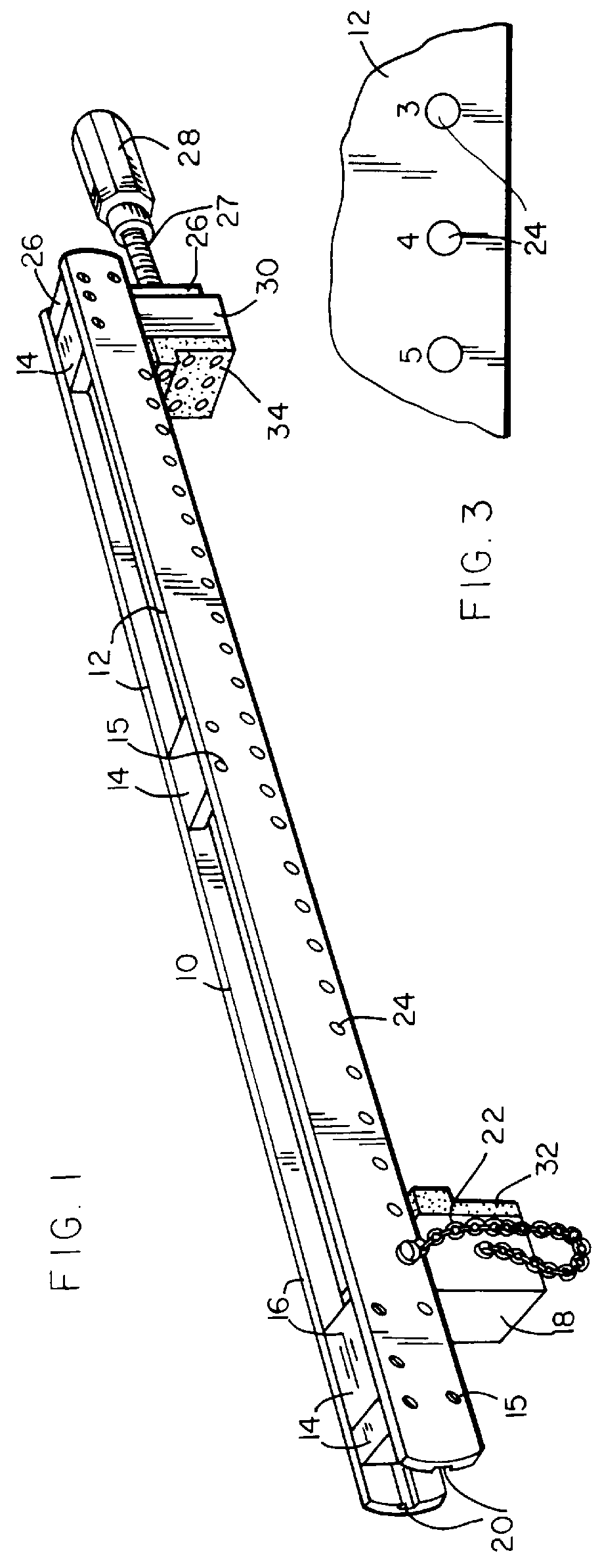
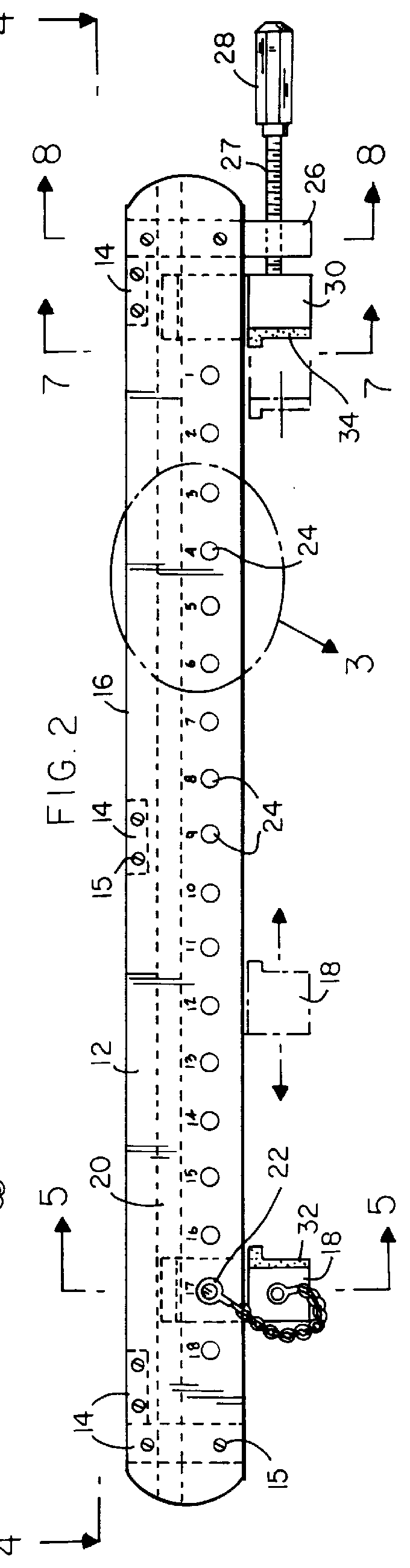
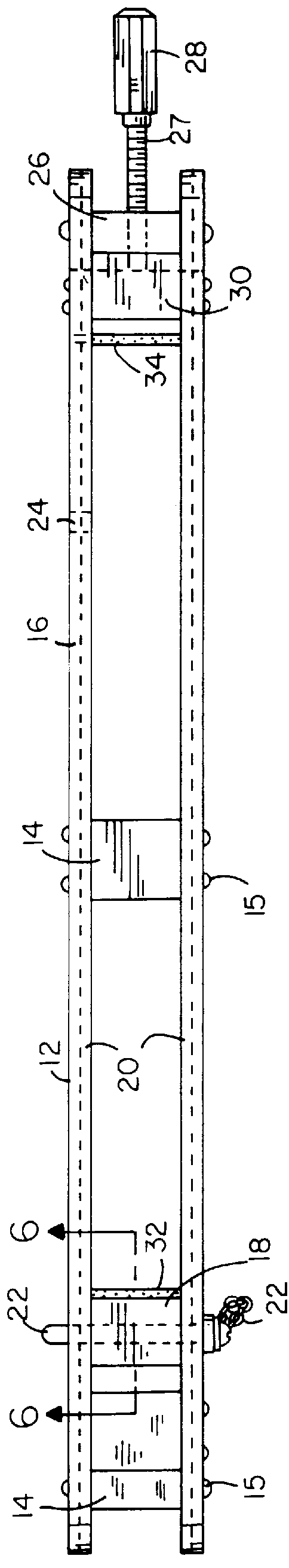
Turning to FIG. 1, therein is shown a perspective view of the present invention shown generally at 10 being a pair of elongated, straight parallel bars 12, attached and secured to each other by multiple brace or spacer pieces 14, located near the ends and middle of the bar 12, for maintaining, strengthening, and attaching the bars to each other to be approximately 1.5 inches apart. The spacer pieces 14, are attached to the bars 12, using fastening means 15, such as screws or nuts and bolts. The bars 12 are composed of lightweight material, such as, aluminum or like material. The top surfaces 16 of the bar 12 and spacers 14 form a flat top surface which is a major advantage of the present invention over the prior art because the flat top surface 16 allows the clamp 10 to be used upside down, i.e., rested on what would normally be the top surface 16, without falling over which occurs with other bar clamps because they are made of round bars which have no flat top surface.

Also shown t...


PUM


Abstract

The present invention provides a bar clamp made of lightweight parallel metal bars, e.g., aluminum, having movable or adjustable contacting attachment bodies which allow the clamp to be used for various applications. The bar clamp of the present invention is equipped with a measurement gauge for accurate attachment of the contacting attachment bodies to the workpiece. The parallel bars are separated and secured to each other by spacers and the bars have tracks along the inner faces of their entire length along which the attachment bodies move. One embodiment of the present invention discloses how the attachment bodies can be replaced by large frames having multiple attachment bodies mounted thereon for holding the workpiece in a vertical or horizontal position. Also, various designs of the attachment bodies which are interchangeable are provided.

Description

1. Field of the InventionThe present invention generally relates to clamping devices for woodworking and, more particularly, is concerned with a bar clamp device for use in wood manufacturing having adjustable clamping attachment bodies which are adaptable for various clamping applications.2. Description of the Prior ArtNumerous woodworking clamps have been described in the prior art. While these woodworking clamps may have been suitable for the purpose for which they were designed, they would not be suitable for the purposes of the present invention as heretofore described. Thus, it is desirable to provide a woodworking clamp useful in wood manufacturing which has removable attachments useable for various clamping applications.The following are clamping devices used in the woodworking industry.Hand screws, or wooden parallel clamps, are holding devices for wood, plastic, and many other materials. They can be used on finished surfaces without any protective wood strips. They are mad...

Claims


Application Information

Patent Timeline
Patent Type & Authority Patents(United States)
IPC IPC(8): B25B1/10B25B1/00B25B1/12B25B1/24B25B5/16B25B5/10B25B5/00
CPCB25B1/10B25B1/12B25B5/163B25B5/10B25B1/241
Inventor DE SOUZA, STEPHEN
Owner DE SOUZA STEPHEN
Why Eureka
Try Eureka